VICMARC® MACHINERY PTY. LTD.
OWNER’S MANUAL
VL150 VL200 VL240 VL300

edition 04/21
Manufacturers of Quality Woodturning Lathes and Accessories
within Australia 07 3284 3103 overseas +61 7 3284 3103

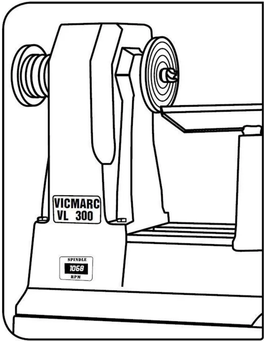
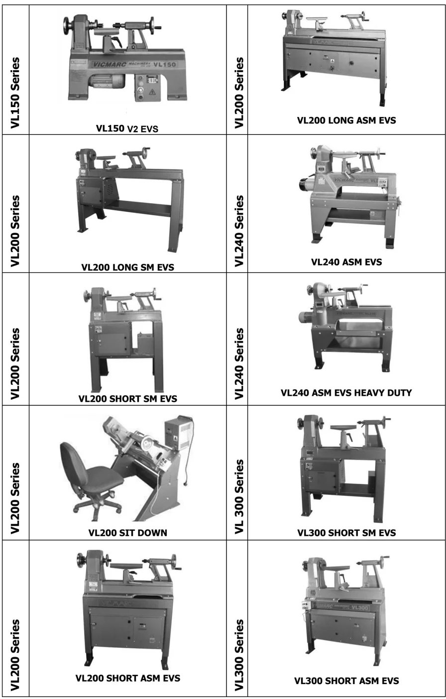
VICMARC® LATHE MODELS
| VL150 Series | VL200 Series | ||
|---|---|---|---|
| VL150 V2 EVS | VL200 LONG ASM EVS | ||
| VL200 Series | VL240 Series | ||
| VL200 LONG SM EVS | VL240 ASM EVS | ||
| VL200 Series | VL240 Series | ||
| VL200 SHORT SM EVS | VL240 ASM EVS HEAVY DUTY | ||
| VL200 Series | VL300 Series | ||
| VL200 SIT DOWN | VL300 SHORT SM EVS | ||
| VL200 Series | VL300 Series | ||
| VL200 SHORT ASM EVS | VL300 SHORT ASM EVS |
VICMARC LATHES P2


VICMARC MACHINERY
PTY.LTD.
Manufacturers of Quality Woodturning Lathes, Chucks and Accessories
Phone (07)3284 3103 Fax (07)3283 4656 Int Ph 61-7 3284 3103 Int Fax 61-7 3283 4656 Email : vicmarc@vicmarc.com Web www.vicmarc.com A : 52 Grice Street Clontarf QLD 4019 Australia
Δ Dear Customer
Thank you for purchasing a Vicmarc® high quality wood lathe and accessories. Please read these instructions carefully and familiarise yourself with in every aspect of the lathe before initiating any project. Please keep this manual in a safe place for future reference.
About Vicmarc® Machinery
Vicmarc® Machinery, a family operated business, has been manufacturing wood turning lathes and accessories for the hobbyist and professional since 1984. Director Victor Verrecchia trained in Switzerland in Engineering and Tool Making. Since 1968 he has been designing and manufacturing all types of machinery. Later his focus turned specifically to designing and manufacturing quality Wood Turning Lathes and accessories. Vicmarc® Lathes and Chucks are known and respected internationally for their unique user friendly design and tough cast iron construction.
Vicmarc® is dedicated in providing to its world wide customers, machinery of the highest quality. Only the best materials and latest high-precision computer-controlled machinery are used in the manufacturing of Vicmarc® Lathes and Accessories. Vicmarc® machinery continues to respond to the demands of the market, updating and improving at all stages of design and manufacture through constant research and development. It is no wonder therefore that Vicmarc® retains its place as a leader Nationally and Internationally in its field.




INDEX
Getting Started
| 1. | SAFETY | 1. | Essential Safety Procedures | P5 |
|---|---|---|---|---|
| 2. | GETTING STARTED | 2.1 | Positioning of Your Lathe | P5 |
| 2.2 | Cleaning | P5 | ||
| 3. | SET-UP | 3.1 | The Correct Work Height | P5-6 |
| 4. | WORKPIECE SAFETY | 4. | Workpiece Diameter And Turning Speeds | P6 |
| 5. | GENERAL MAINTENANCE | 5. | General Maintenance And Operating Tips | P6 |
| 6. | ELECTRICAL INFORMATION | 6. | Important Electrical Information | P7 |
| 7. | FAMILIARISATION | 7.1 | Lathe Overview | P7 |
| 7.2 | Key Component Description | P8 | ||
| 8. | START UP PROCEDURE | 8. | Startup Procedure for your new lathe | P9 |
Lathe Maintenance Procedures
| 9. | VL150 LATHE | 9.0 | Lathe Description | P9 |
|---|---|---|---|---|
| 9.1 | Spindle Pulley Speeds | P10 | ||
| 9.2 | Setting Up the Tailstock | P10 | ||
| 9.3 | Setting Up the Camlock | P10 | ||
| 9.4 | Mounting and Removing the Chuck | P10-11 | ||
| 9.5 | Ejecting the Morse Taper | P11 | ||
| 9.6 | Changing the Belt Ratio | P11 | ||
| 9.7 | Replacing the Belt | P11-12 | ||
| 9.8 | Servicing the Tailstock | P12 | ||
| 9.9 | Servicing the Camlock | P13 | ||
| 9.10 | VL150 Exploded Views and Wiring Diagram | P13-16 | ||
| 10. | VL240 LATHE | 10.0 | Lathe Description | P17 |
| 10.1 | Spindle Pulley Speeds | P17 | ||
| 10.2 | Rotating the Index Head | P17 | ||
| 10.3 | Changing the Belt Ratio | P17 | ||
| 10.4 | VL240 Exploded Views and Wiring Diagram | P18-19 | ||
| 11. | VL200/300 LATHE | 11.0 | Lathe Description | P20 |
| 11.1 | Spindle Pulley Speeds | P20 | ||
| 11.2 | VL200/300 Exploded Views and Wiring Diagram | P20-22 | ||
| 12. | VL200/240/300 LATHE | 12.1 | Setting Up the Tailstock | P24 |
| 12.2 | Ejecting the Morse Taper | P24 | ||
| 12.3 | Servicing the Tailstock | P24-25 | ||
| 12.4 | Setting Up the Camlock | P25 | ||
| 12.5 | Servicing the Camlock | P25 | ||
| 12.6 | Setting Up the Safety Ring | P25 | ||
| 12.7 | Changing the Belt Ratio | P25 | ||
| 12.8 | Mounting and Removing the Chuck | P26 | ||
| 12.9 | Outboard Turning Set Up | P26 | ||
| 12.10 | Replacing the Belt | P27 |
General Information
| 13. | TROUBLESHOOTING | P28 | ||
|---|---|---|---|---|
| 14. | LATHE SPECIFICATIONS | P29 | ||
| 15. | TECHNICAL INFORMATION | P30 |
VM VIGMARC LATHES P4

1. SAFETY
- READ AND UNDERSTAND THE INSTRUCTION MANUAL BEFORE OPERATING WOOD LATHE.
- Do not operate while under the influence of drugs, alcohol or medication.
- Switch main power off when machine is not in use.
- The power supply to the electronic unit needs to be turned off when not in use
- Do not attempt to turn without having had some woodturning lessons.
- Do not wear gloves, neckties, jewelry or loose clothing.
- Always wear eye protection and a dust mask.
- Do not operate without guards in place. Always close the cover before operating.
- Rough out the work piece before installing on the faceplate.
- Do not mount a split work piece or one containing knots.
- Tighten all Camlocks before operating.
- Ensure the work piece does not move on the mount while it is being turned.
- Ensure that the indexing pin is disengaged by rotating the work piece by hand before applying power.
- Use low RPM when starting a new work piece and do not exceed permitted Rpm (Revolutions per minute). (Refer to page 6 under Workpiece Diameter & Turning Speeds).
- Allow the lathe to come to a complete stop before changing direction of turning.
- Disconnect machine from power source before proceeding with any maintenance or any adjustments.
- Ensure the switch is in the OFF position before plugging into the power source.
- Remove the tool rest, or move the Camlock to the side before sanding or polishing.
- If available we recommend using a dust extraction apparatus.
2. GETTING STARTED
2.1 The Positioning of Your Lathe
- Before unpacking your lathe, decide where it is to be placed and clear the floor area. Preferably choose a level area, with sufficient room around for any maintenance required. (Recommended is 800mm clearance all around).
- Confirm that you have a suitable power outlet close to the chosen lathe location eliminating any unnecessary extension leads. (Refer to "IMPORTANT ELECTRICAL INFORMATION" Item 6, page 7)
- Position your lathe after unpacking in the designated area.
- Set-up your lathe to your correct work height according to the recommendations made in the correct work height in item 3.1, pages 5-6.
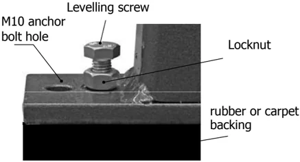
- It is not always necessary to anchor down the lathe, as the weight of the lathe will be sufficient to hold it down in most applications. Anti-vibration pads under each leg are recommended to minimise vibration and floor damage. For your personal safety, it is recommended to anchor down your lathe.
- If lathe is to be anchored to the floor, anti-vibration pads such as rubber or carpet pieces should be used
- Place spirit level on your lathe bed. Make it level by adjusting the levelling screws on each corner of the lathe.
- It is recommended to use M10 concrete anchor bolts to anchor the lathe. (Refer below)
- After satisfactory position and levelling has been achieved, tighten the locknuts. (Refer below)
- Be cautious not to twist the machine by tightening the anchor bolts when the machine has not levelled first.

Levelling screw M10 anchor bolt hole Locknut rubber or carpet backing
2.2 Cleaning
- The Manufacturer Vicmarc® Machinery has applied a thick corrosion protective coating to ensure the lathe reaches you in optimum condition. Use white spirits or similar product to remove the protective coating.
- In order to keep the machine in top condition, spray all exposed metal areas with light viscosity oil. This minimises corrosion.
- To ensure maximum longevity for your machine, remove all sawdust then re-oil the surfaces after every use.
3. SET UP
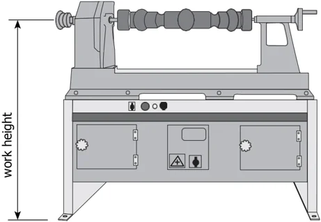
3.1 The Correct Work Height
- The correct height of the lathe is important. It not only minimises fatigue but it also increases the safety aspect for the user and encourages comfortable turning.
- The work height is different for every user.
- The work height is also dependant on the type of work performed.
- The recommended work heights are as shown below.
3. SET UP
3.1 The Correct Work Height
| Height of Operator | Calculated Work height | ||
|---|---|---|---|
| 160cm | 63" | 100cm | 39" |
| 165cm | 65" | 102.5cm | 40" |
| 170cm | 67" | 105cm | 41" |
| 175cm | 69" | 107.5cm | 42" |
| 180cm | 71" | 110cm | 43" |
| 185cm | 73" | 112.5cm | 44" |
| 190cm | 75" | 117.5cm | 46" |
| 195cm | 77" | 120cm | 47" |

Note. The Subjective Preference of the Turner
The above results in table one were achieved from a study of 4500 turners the following guide can be used in setting up your lathe. As a rule of thumb use the height of the turner and subtract 60-75cm (= the recommended work height. You may wish to use your personal preference. The above table one should be used as a starting point. For all machine models, calculated work height is measured from the floor to the centre of the spindle.
4. WORKPIECE TURNING DIAMETER and TURNING SPEEDS

Ø 450mm 400rpm
Ø 400mm 500rpm
Ø 350mm 550rpm
Ø 300mm 650rpm
Ø 250mm 800rpm
Ø 200mm 1000rpm
Ø 150mm 1300rpm
Ø 100mm 2000rpm
Caution!
The turning speeds are only to be used as a general guide and are starting speeds for your work piece. Due to different wood types and wood thicknesses etc. different speeds may be necessary for optimal and safe turning.
5. GENERAL MAINTENANCE AND OPERATING TIPS
-
IMPORTANT.
Refer to item 6 electrical information below. -
All EVS machines come with a 220 – 240V AC inverter. Settings for the unit have been programmed to suit the lathe that it was fitted to and should not be tampered with. Tampering with the inverter unit will void all warranty claims.
-
Make sure that the lathe is positioned level on the workshop floor. It is important that rubber padding or carpet is placed under the steel stand to separate it from the floor to reduce vibration. The lathe may be bolted to the floor if required. If bolting the lathe to the floor, make sure that the lathe stand sits level to the ground. (Refer to levelling your lathe page5)
-
Ensure the switch is in the OFF position before plugging into the power source.
-
Before starting the lathe make sure the indexing pin is not engaged to prevent the drive belt from being damaged.
-
If turning inboard clockwise or outboard anti-clockwise, use the safety ring (Refer to Setting up the safety ring 12.6, Page 25) in order to prevent your work piece from coming undone.
-
Note. If the spindle overheats (too hot to touch), engage the indexing pin, loosen the three grub screws, back off the bearing adjustment nut (handwheel on the VL100) by rotating 2-5 degrees anticlockwise, retighten the grub screws evenly. Once tight, disengage the indexing pin and turn the spindle by hand making sure that the spindle turns freely without any tight spots.
-
Before turning, always manually rotate the work to ensure that it clears all parts of the lathe.
-
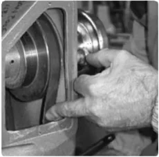
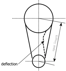
Do not over tighten the belt. Tighten with a deflection of 10-15mm.
-
When engaging the indexing pin, do not use excessive force to remove or tighten any of the faceplates or chucks.
-
It is not recommended to run the lathe for an extended period of time at low rpm as this could cause overheating and although the motor has thermal protection, abuse can still damage the motor.
-
If the motor trips out from overheating, allow it to cool for 15-20 mins before continuing turning.
-
If the lathe is not to be used for an extended period of time, it is recommended that the lathe be disconnected from the power source/mains supply.
VIGMARC LATHES P6
6. IMPORTANT ELECTRICAL INFORMATION
- Please ensure that the circuit for the power outlet is earthed and protected by at least a 15-20 - amp circuit breaker.
- The lathe electronics is provided with an RFI(Radio Frequency Interference) filter which is designed to leak up to 5 milliamps. Due to earth leakage of more than 15 milliamps from other appliances in the same circuit tripping may occur. That is why it is recommended that a dedicated power circuit for the lathe be installed.
- Some brands of earth leakage switches are more susceptible to the conducted RFI. If excessive tripping still occurs when the lathe is on a separate circuit then contact your local electrician. The electrician can check with the supplier of the earth leakage switch, checking its suitability for the use with single phase supply output AC Variable Speed Drives.
- We strongly recommend any work on your power supply to the lathe or the electrical system of the lathe should be performed by a qualified and licensed electrician.
- For optimum results make sure that the lead to the power supply is no longer than three meters. Leads longer than three meters can cause amperage-rating fluctuation and affect the lathes performance.
7. FAMILIARISATION
7.1 Overview
○ Before starting to use your Vicmarc® Lathe it is important that you familiarise yourself with all aspects and parts of the lathe. The below picture will give you a parts description.
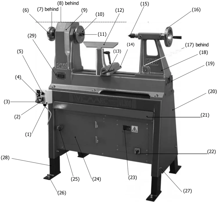
| No. | Description | No. | Description | No. | Description |
|---|---|---|---|---|---|
| 1 | Remote Switch Box | 11 | Drive Dog | 21 | Stop Bar |
| 2 | Reverse Button | 12 | Toolrest | 22 | Main Switch |
| 3 | Off Button | 13 | Camlock Locking Lever | 23 | Digital Display Unit (electronic models only) |
| 4 | On Button | 14 | Camlock | 24 | Motor Access Door |
| 5 | Speed Controller | 15 | Live Centre | 25 | Motor Access Door Lock |
| 6 | Handbrake Wheel | 16 | Hand Wheel | 26 | Lathe Levelling Bolts |
| 7 | Indexing Pin | 17 | Tailstock Locking Lever | 27 | Height Positioning Bolt x 4 |
| 8 | Indexing View Glass | 18 | Tailstock | 28 | Adjustable Legs |
| 9 | Headstock | 19 | Bed | 29 | RPM LED Display |
| 10 | Faceplate | 20 | Stand |

7.2 Key Component Description (items refer to page 7, 7.1 overview)
Item 2 - Reverse Button This button enables you to turn in reverse. However it is important that when choosing to turn in reverse you make sure the lathe has come to a complete stop. Caution, use the safety ring as described on page 25 when reverse turning. The quality of sanding can be improved and provide a smoother finish by altering the direction of rotation.
Item 3 / 4 - On & Off Buttons Before starting your lathe, rotate your work piece one rotation using the Handbrake Wheel (Item 6). This will ensure the work piece has sufficient clearance. If the work piece does not rotate, make sure the indexing pin (Item 7) is disengaged. The lathe has a soft start of 3 seconds and a 4 second stop. These settings should not be changed as these have been factory set for your safety.

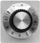
Item 5 - Speed Controller Is used to adjust the speed of the lathe, 0 – slowest 10 – fastest, actual motor speed displayed on the digital display unit (Item 22)
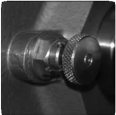
Item 7 - Indexing Pin To engage the indexing pin rotate the head of the pin 90° until it slides inwards, then rotate the handbrake wheel (item 6) until the pin engages preventing the spindle from rotating. To disengage pull out the pin and rotate the head 90°.
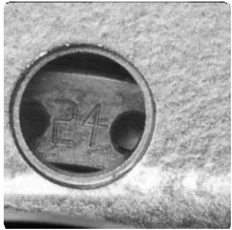
Item 8 - Index Viewing Glass All lathes have 24 indexing holes in the back of the spindle, which are used for indexing and locking the spindle. Each hole represents 15 degrees for indexing purposes.
Item 21 - Stop Bar Designed for safety and to be controlled primarily by the operator’s leg. It works the same as the Off Button (Item 4).
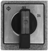
Item 22 - Main Switch This switch disconnects all power to the lathe and should be turned off when the machine is not in use.
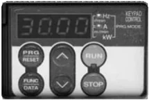
Item 23 - Digital Display Unit This displays the speed of the motor and is controlled by the Speed Controller (Item 5). For actual spindle speeds available refer to “Spindle Speed” under your lathe model.
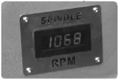
Item 29 - RPM LED Display This displays the speed of the spindle and is controlled by the Speed Controller (Item 5).

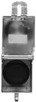


8. START UP PROCEDURE FOR YOUR LATHE
Important! Remember your safety is a priority!
- Ensure you have set up your lathe correctly as per page 5 and that you have connected your power lead from the lathe to the nearest power point as per “important electrical information” on page 7
- Turn the main switch (item 22) clockwise (see page 7 for location).
- By now the EVSD (electronic variable speed device) will give a digital readout by flashing. (item 23 page 7)
- You can now select the rpm required by adjusting the speed controller (potentiometer) (item 5). The rpm you select will appear flashing on the digital readout.
- Please ensure that the spindle is not locked with the indexing pin (item 7 on page 7).
- After placing your work piece first make sure it can be rotated by hand. Start up your lathe on low rpm. Refer to work piece diameter and turning speed information on page 6. IMPORTANT: For the work piece diameter and turning speeds you must familiarize yourself with the information on page 6. The spindle pulley ratio information is near the beginning of the section for your particular lathe.
- Depress the on button (item 4 on page 7) this will introduce power to the motor and activate the lathe. Note: the rpm, which is displayed, is the rpm at which the motor is currently operating.
- Because of different densities within the timber, we recommend to gradually increase your speed as your work piece allows, without allowing your lathe to vibrate.
- Increased vibration can cause work piece to come off its holding position.
- For extra safety use tailstock with live centre to support work piece.
- The electronic motor will reach its selected speed within three seconds, and it will take only 4 seconds to come to a full stop.
- WARNING: Do not attempt to stop manually with your hand the break wheel within the 4 seconds as it can cause skin burn.
- To stop your lathe the stop bar can be used. Refer to item 21 on page 7.
- Please refer to the safety instruction on page 5 and safety ring set up on page 25.
9. LATHE VL150
 VL150 V2 EVS
Description
The VL150 V2 EVS (Electronic Variable Speed) provides excellent performance with up to 150% torque on low RPM. This lathe has a powerful 0.75kW motor which allows for spindle speeds from 30-3460 RPM. The full cast iron construction makes this an extremely rigid and high performing lathe. The electronics and switch gear are mounted in a moveable steel box which enables the turner to customise their set up in a convenient way.
First to introduce MT2, and taper roller bearings on this size lathe. The Vicmarc VL150 lathe is in a class of its own when compared to other midi lathes on the market. The best value feature-by-feature of any midi lathe sold in the world, this lathe is made to last a lifetime. Vicmarc is clearly the midi lathe of choice for those seeking a quality compact lathe.
9. LATHE VL150
9.1 Spindle Pulley Speeds
It is important that the belt is on the right pulley for the speed required. Not doing so can cause the motor to overheat. Below is a representation of the headstock pulleys and their equivalent ratio’s.
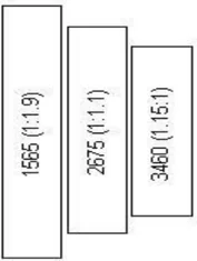
Maximum speed for the three step pulley
| Pulley Ratio | |||
|---|---|---|---|
| Readout | 1.15:1 | 1:1.1 | 1:1.9 |
| 3000 | 3460 | 2675 | 1565 |
| 2500 | 2875 | 2272 | 1315 |
| 2000 | 2300 | 1818 | 1053 |
| 1500 | 1725 | 1363 | 789 |
| 1000 | 1150 | 909 | 526 |
| 500 | 575 | 454 | 263 |
| 250 | 288 | 227 | 132 |
| 100 | 115 | 90 | 53 |
| 30 | 35 | 27 | 16 |
9.2 Setting up the Tailstock
The eccentric locking mechanism of the tailstock is factory preset. If adjusting is necessary the following steps are applicable:
- Slide tailstock to the end of the bed as illustrated.
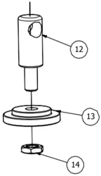
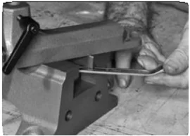
- Undo the M10 locking nut item 14 (clockwise is loosening and anticlockwise is tightening) with a 16mm open end spanner, then rotate the clamping plate clockwise to tighten.
- Lock the Tail stock with locking lever, if lever is in the correct position is at eleven o’clock Re-lock the locking nut.
- The tailstock lever can be swapped to the opposite side of the tailstock if preferred. Simply remove the circlip and reposition the bush and tailstock locking lever to the opposite side.
9.3 Setting up the Camlock
The eccentric locking mechanism of the Camlock is factory preset. If adjusting is necessary the following steps are applicable:
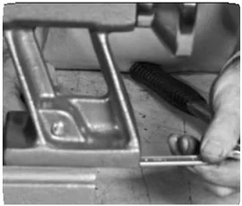
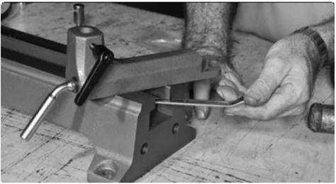
- Remove Tailstock than slide Camlock to the end of the bed as illustrated.
- Undo the M10 locking nut item 7 (clockwise is loosening and anticlockwise is tightening) with a 16mm open end spanner, then rotate the clamping plate clockwise to tighten.
- Lock the Camlock with locking lever, if lever is in the correct position is at four or eight o clock, re-lock the locking nut. (Camlock is designed to lock in both directions)
9.4 Mounting and Removing the Chuck
Mounting
Before mounting the chuck, make sure that the threads are clean and free of grit.
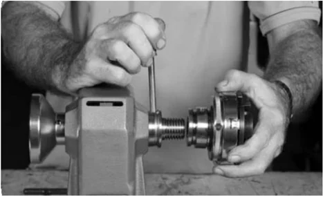
- Place the tommy bar (supplied with Vicmarc® Chuck) into the spindle to hold it in place.
- Mount the chuck on the lathe, carefully place the chuck on the thread, making sure it is square.
- Turn the chuck slowly to screw on the chuck until it is tight.
- The machine should never be turned on for this procedure.
VM VICMARC LATHES P10

9. LATHE VL150
9.4 Mounting and Removing the Chuck
Removing
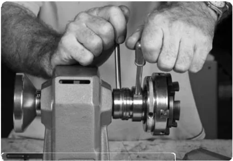
- Place the tommy bar into the spindle to hold it in place as in mounting.
- Place the other bar into the chuck and push firmly to unbind the chuck thread.
- Use a light tap with the hand or a soft mallet (never use a metal one) to unbind the thread if necessary.
- Once the thread is unbound unwind the chuck while holding the spindle secure with the tommy bar.
Tip: If you have continued problems removing the chuck, a thin PVC (nylon) washer can be between the face of the chuck and the face of the spindle before the chuck is screwed on. This prevents metal to metal binding which can make it difficult to remove the chuck.
9.5 Ejecting the Morse Taper
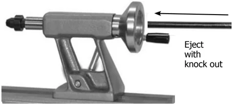
The taper is removed by using the knock out bar. The knock out bar is placed into the end of the tailstock and taps the taper out (a soft hammer can be used on the knock out bar if necessary).
Eject with knock out
9.6 Changing the Belt Ratio
Depending on the size of the work piece to be turned (see Turning Diameter and Turning Speeds Page 6) the belt ratio may require changing for different speeds.
- Before commencing any maintenance work on the machine, make sure that the main switch is in the off position.
- Loosen the clamp lever and lift up the motor to loosen the belt.
- Once loosened, seat the belt precisely on the correct pulley ratio.
- Re-tension the belt.
9.7 Replacing the Belt
Removing the Belt:
- Make sure that the lathe is turned off at the main switch.
- Measure the distance between the largest pulley and the inside of the headstock so that the pulley can be re-installed at the exact same original position.
- Loosen the belt as per changing the belt ratio.
- Loosen the grub screws on the handbrake wheel.
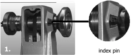
- Engage the indexing pin and unscrew the handbrake wheel clockwise and remove.
- Loosen the grub screw on the middle-sized pulley with an Allen key.
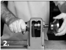
- From the hand wheel side, lightly tap the spindle with a rubber mallet making sure that it stays horizontal avoiding damage to the key way.
- Ensure that the taper roller bearing on the handbrake wheel side does not fallout.
- Remove the spindle ensuring that the pulleys are not allowed to drop down into the headstock.
- Place the spindle in a clean place and pull out the pulley.
- The belt can now be removed, making way for a new belt.
index pin
-
VL150 LATHE
9. VL150 LATHE
Re-Assembly of the Belt
- Sit the new belt on the pulley and place back into headstock.
- When re-inserting the spindle, make sure that the key on the spindle lines up with the keyway to avoid any damage.
- Line up the pulley back in its original position and re-tighten the grub screw in the middle pulley.
- Screw the handbrake wheel back on until there is no axial play in the spindle and tighten the grub screws.
- Hook belt around the motor pulley and tighten the belt adjustment. Check the belt deflection to ensure the correct tension. (see page 17)
- Once assembled replace all covers, disengage the indexing pin and turn spindle by the hand wheel to check for hard spots.
- Turn the machine on at the mains switch and run the machine at moderate Rpm (approx. 1500 rpm) for five minutes to check the operation of the machine.
- If the pulley housing gets hotter than luke warm to touch after 5 minutes of operation then stop the machine, loosen the handwheel grub screws and unscrew the handbrake wheel approx. 2 to 5 degrees then re-tighten the grub screws.
- VL150 LATHE
9.8 Servicing the Tailstock
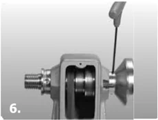
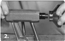
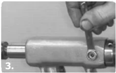
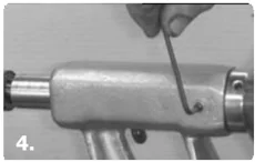
Removing the Quill on the Tailstock:
-
Lock the tailstock onto the bed using the locking lever.
-
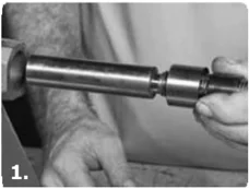
Turn the hand wheel so that 20-25mm of the quill is protruding from the front of thetailstock.
-
Loosen the grub screws on the handle two or three revolutions.
-
Pull off the handwheel.
-
Loosen the nuts on both sides of the tailstock, then remove the grub screws.
-
The quill can now be removed from thetailstock
-
The quill can now be cleaned along with the inside of the tailstock.
-
Note. Never use sandpaper to clean the quill and take care not to remove the key piece at the end of the locking lever while cleaning.
-
All mobile parts should now be greased with a high quality grease or graphite grease before re-assembly.
Re-Assembling the Quill on the Tailstock:
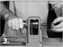
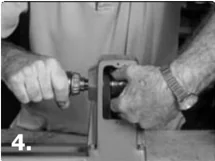
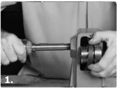
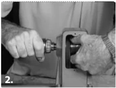
- The quill should be re-placed from the back of the tailstock making sure that it is horizontal to the bore.
- Push the quill back into place and align the keyway into the key piece.
- Realign the drill marks in the tailstock bush to the grub screw holes and retighten the grub screws equally. Then retighten both nuts.
- Replace the hand wheel and tighten the grub screws.
- Turn the hand wheel. If it does not run smoothly (i.e. slight gripping or scraping) several light taps on the hand wheel with rubber hammer will bring the quill into alignment.
- The free play of the hand wheel should be no more than 10 degrees.

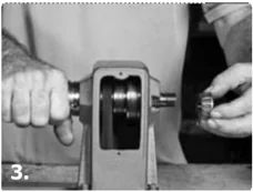
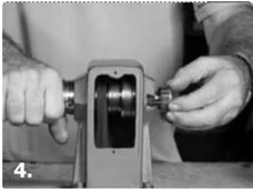
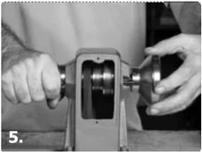
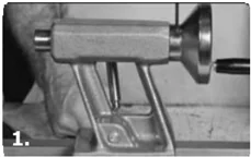
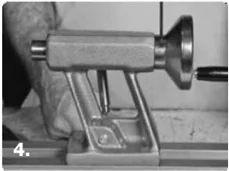
9. LATHE VL150
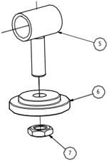
9.9 Servicing the Camlock (see view below)
- Undo the two circlips (item 4).
- Reach underneath and support the clamping plate. (item 6)
- Slide out the Camlock bar. (item 8)
- Thoroughly clean the shaft and the bore.
- Re-grease the shaft with a high quality bearing grease.
- To re-assemble, slide in the shaft through the bore and the Camlock T-Connector (item 5).
- Replace the circlips.
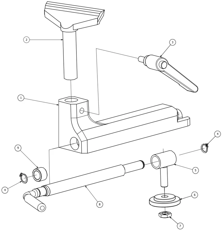
9.12 VL150 Exploded Views - Camlock
| VL150 Camlock | |||
|---|---|---|---|
| No. | Qty | Part No. | Description |
| 1 | 1 | V00196 | Camlock |
| 2 | 1 | V01164 | Toolrest, 150mm |
| 3 | 1 | P00398 | Adjustable Handle, M8 x 20 |
| 4 | 2 | P00242 | Circlip, External 12mm |
| 5 | 1 | V00305 | Camlock T- Connector |
| 6 | 1 | V00905 | Clamping Plate, 31mm |
| 7 | 1 | P00510 | Hex Nut, M10 |
| 8 | 1 | V00790 | Camlock Lever |
| 9 | 1 | Camlock Lever Bush |
9. VL150 LATHE
9.10 VL150 Exploded Views - Stand
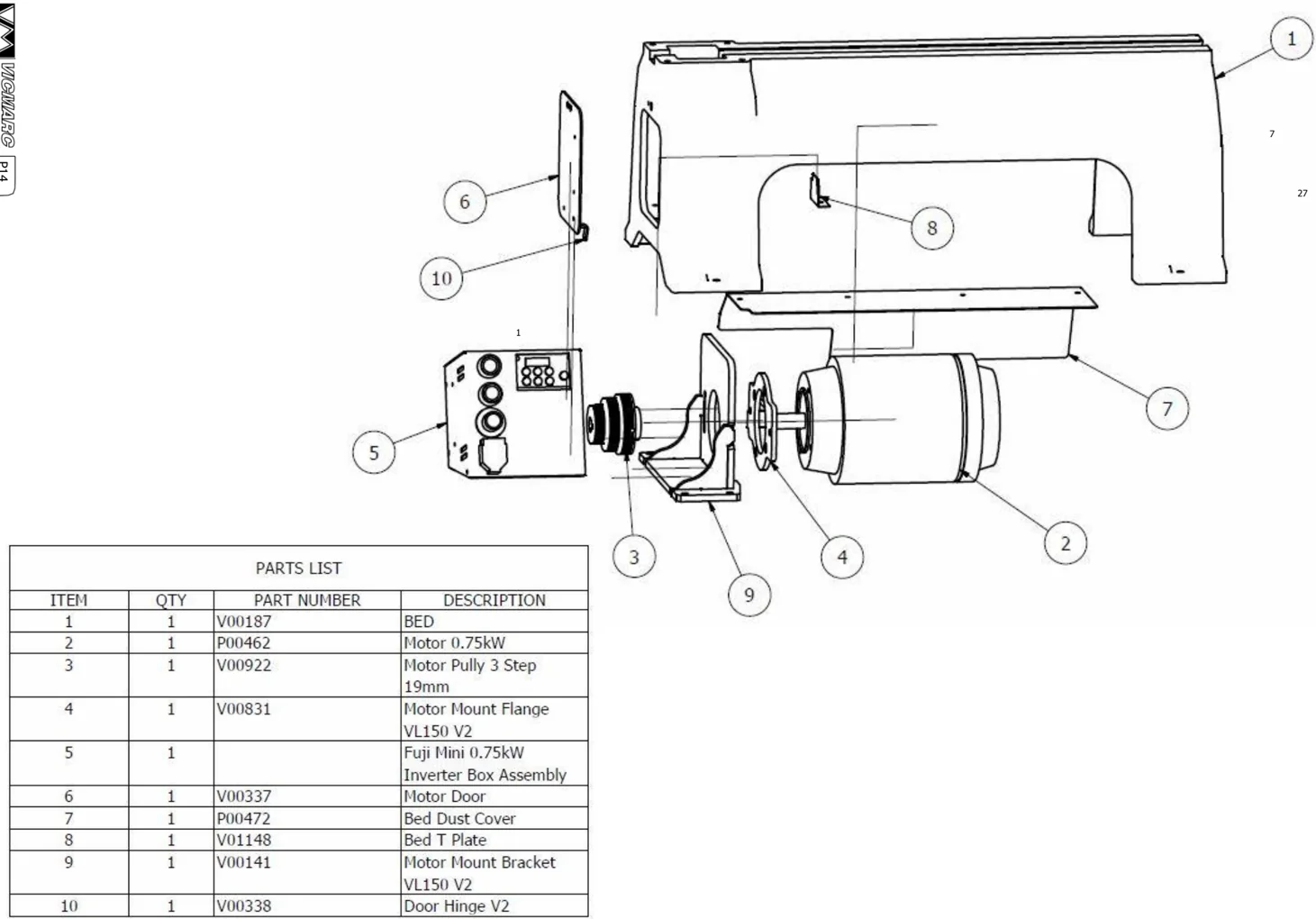
PARTS LIST
| ITEM | QTY | PART NUMBER | DESCRIPTION |
|---|---|---|---|
| 1 | 1 | V00187 | BED |
| 2 | 1 | P00462 | Motor 0.75kW |
| 3 | 1 | V00922 | Motor Pully 3 Step 19mm |
| 4 | 1 | V00831 | Motor Mount Flange VL150 V2 |
| 5 | 1 | Fuji Mini 0.75kW Inverter Box Assembly | |
| 6 | 1 | V00337 | Motor Door |
| 7 | 1 | P00472 | Bed Dust Cover |
| 8 | 1 | V01148 | Bed T Plate |
| 9 | 1 | V00141 | Motor Mount Bracket VL150 V2 |
| 10 | 1 | V00338 | Door Hinge V2 |
9. LATHE VL150
9.10 VL150 Exploded Views - Headstock
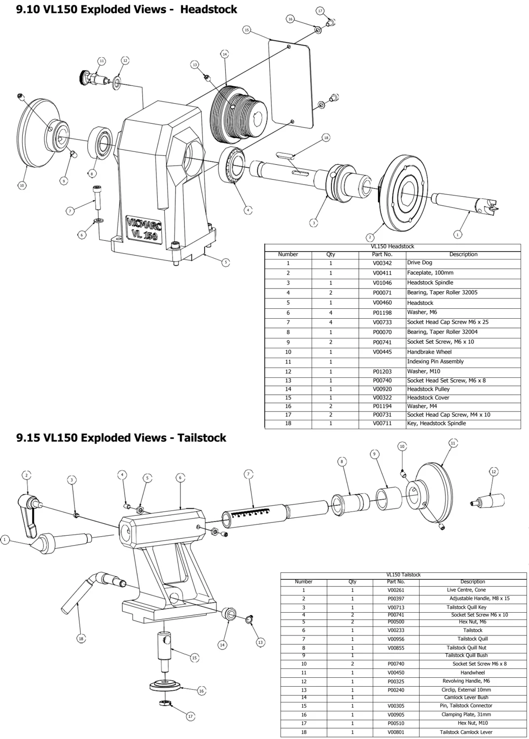
| VL150 Headstock | |||
|---|---|---|---|
| Number | Qty | Part No. | Description |
| 1 | 1 | V00342 | Drive Dog |
| 2 | 1 | V00411 | Faceplate, 100mm |
| 3 | 1 | V01046 | Headstock Spindle |
| 4 | 2 | P00071 | Bearing, Taper Roller 32005 |
| 5 | 1 | V00460 | Headstock |
| 6 | 4 | P01198 | Washer, M6 |
| 7 | 4 | V00733 | Socket Head Cap Screw M6 x 25 |
| 8 | 1 | P00070 | Bearing, Taper Roller 32004 |
| 9 | 2 | P00741 | Socket Set Screw, M6 x 10 |
| 10 | 1 | V00445 | Handbrake Wheel |
| 11 | 1 | Indexing Pin Assembly | |
| 12 | 1 | P01203 | Washer, M10 |
| 13 | 1 | P00740 | Socket Head Set Screw, M6 x 8 |
| 14 | 1 | V00920 | Headstock Pulley |
| 15 | 1 | V00322 | Headstock Cover |
| 16 | 2 | P01194 | Washer, M4 |
| 17 | 2 | P00731 | Socket Head Cap Screw, M4 x 10 |
| 18 | 1 | V00711 | Key, Headstock Spindle |
9.15 VL150 Exploded Views - Tailstock

| VL150 Tailstock | |||
|---|---|---|---|
| Number | Qty | Part No. | Description |
| 1 | 1 | V00261 | Live Centre, Cone |
| 2 | 1 | P00397 | Adjustable Handle, M8 x 15 |
| 3 | 1 | V00713 | Tailstock Quill Key |
| 4 | 2 | P00741 | Socket Set Screw M6 x 10 |
| 5 | 2 | P00500 | Hex Nut, M6 |
| 6 | 1 | V00233 | Tailstock |
| 7 | 1 | V00956 | Tailstock Quill |
| 8 | 1 | V00855 | Tailstock Quill Nut |
| 9 | 1 | Tailstock Quill Bush | |
| 10 | 2 | P00740 | Socket Set Screw M6 x 8 |
| 11 | 1 | V00450 | Handwheel |
| 12 | 1 | P00325 | Revolving Handle, M6 |
| 13 | 1 | P00240 | Circlip, External 10mm |
| 14 | 1 | Camlock Lever Bush | |
| 15 | 1 | V00305 | Pin, Tailstock Connector |
| 16 | 1 | V00905 | Clamping Plate, 31mm |
| 17 | 1 | P00510 | Hex Nut, M10 |
| 18 | 1 | V00801 | Tailstock Camlock Lever |
9. VL150 LATHE
9.10 VL150 - Wiring Diagram
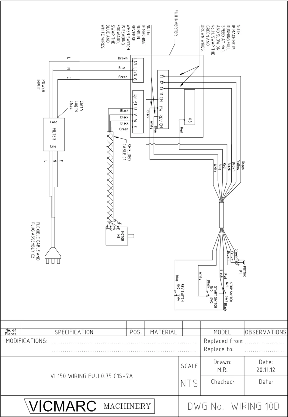
| No. of Pieces | SPECIFICATION | POS. | MATERIAL | MODEL | OBSERVATIONS |
|---|---|---|---|---|---|
| MODIFICATIONS: | Replaced from: | ||||
| Replace to: | |||||
| VL150 WIRING FUJI 0.75 C1S-7A | SCALE NTS | Drawn: M.R. | Date: 20.11.12 | ||
| Checked: | Date: | ||||
| VICMARC MACHINERY | DWG No. WIRING 10D |
P16

10. LATHE VL240
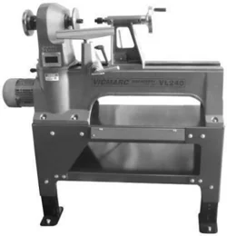
VL240 ASM EVS HEAVY DUTY

Electronic Unit
Control Box
Flat Pack Stand can also be purchased separately.
Part No. V01082
Lathe Models 200,240 and 300 are equipped with the same headstock spindle, tailstock spindle, handwheels, handbrake wheels and bearings. Therefore all adjustments and assembly methods on the headstock and the tailstock on those models are the same. The Camlock assemblies are of the same system but different sizes.
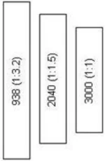
10.1 Spindle Pulley Speeds
It is important that the belt is on the right pulley for the speed required. Not doing so can cause the motor to overheat. Below is a representation of the headstock pulleys and their equivalent ratio’s.
Maximum Speed for the 3 step pulley
| Pulley Ratio | |||
|---|---|---|---|
| Readout | 1:1 | 1:1.5 | 1:3.2 |
| 3000 | 3000 | 2040 | 938 |
| 2500 | 2500 | 1667 | 781 |
| 2000 | 2000 | 1333 | 625 |
| 1500 | 1500 | 1000 | 469 |
| 1000 | 1000 | 667 | 312 |
| 500 | 500 | 333 | 156 |
| 250 | 250 | 167 | 78 |
| 100 | 100 | 67 | 32 |
| 30 | 30 | 20 | 10 |
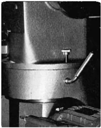
10.2 Rotating The Index Head
- Undo the headstock-locking lever.
- Lift the headstock-locking pin.
- Swivel the headstock to preferred angle in a clockwise direction (indexed at 30 degree increments - 0°, 30°, 60° and 90°).
- Re-insert the headstock locking pin.
- Relock the headstock-locking lever after making the adjustment.
- Important: Make sure the locking lever is in locked position when lathe is in operation.
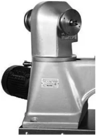
10.3 Changing the Belt Ratio
Depending on the size of the work piece to be turned (see Turning Diameter and Turning Speeds Page 6) the belt ratio may require changing for different speeds.
- Before commencing any maintenance work with the machine, make sure the mains switch is in the off position.
- Adjust the Headstock so that the spindle is parallel to the lathe bed.
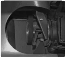
- Unscrew the motor pulley cover and remove.
- Loosen the locking handle and lift the motor to release the belt tension.
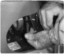
- Once loosened, seat the belt precisely on the correct pulley ratio.
- Re-tension the belt with a maximum deflection of 10-15mm (do not over tighten as it can cause motor bearing problems) see page 17.
- Re-tighten the locking handle.
- Replace all covers before turning machine on.

10. VL240 LATHE
10.4 VL240 Exploded Views - Camlock - Tailstock
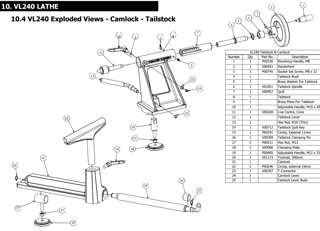
| VL240 Tailstock & Camlock | |||
|---|---|---|---|
| Number | Qty | Part No. | Description |
| 1 | 1 | P00326 | Revolving Handle, M8 |
| 2 | 1 | V00451 | Handwheel |
| 3 | 3 | P00745 | Socket Set Screw, M8 x 12 |
| 4 | 1 | Tailstock Bush | |
| 5 | 1 | Brass Washer For Tailstock | |
| 6 | 1 | V01051 | Tailstock Spindle |
| 7 | 1 | V00957 | Quill |
| 8 | 1 | Tailstock | |
| 9 | 1 | Brass Piece For Tailstock | |
| 10 | 1 | Adjustable Handle, M10 x 20 | |
| 11 | 1 | V00269 | Live Centre, Cone |
| 12 | 1 | Tailstock Lever | |
| 13 | 1 | Hex Nut, M10 (Thin) | |
| 14 | 1 | V00712 | Tailstock Quill Key |
| 15 | 1 | P00241 | Circlip, External 11mm |
| 16 | 1 | V00309 | Tailstock Clamping Pin |
| 17 | 2 | P00511 | Hex Nut, M12 |
| 18 | 2 | V00906 | Clamping Plate |
| 19 | 1 | P00405 | Adjustable Handle, M12 x 25 |
| 20 | 1 | V01173 | Toolrest, 300mm |
| 21 | 1 | Camlock | |
| 22 | 2 | P00246 | Circlip, external 19mm |
| 23 | 1 | V00307 | T-Connector |
| 24 | 1 | Camlock Lever | |
| 25 | 1 | Camlock Lever Bush |
10.4 VL240 Exploded Views - Motor Mount
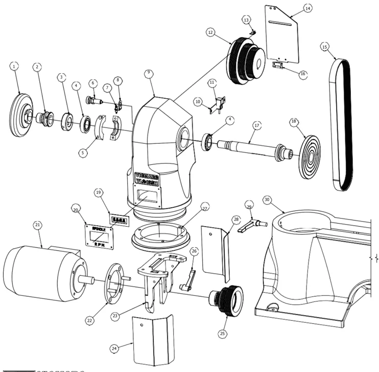
| VL240 Headstock & Motor mount | |||
|---|---|---|---|
| Number | Qty | Part No. | Description |
| 1 | 1 | V00446 | Handbrake Wheel |
| 2 | 1 | V00013 | Rear Spindle Adaptor |
| 3 | 1 | V00851 | Bearing Adjustment Nut |
| 4 | 2 | P00072 | Bearing Taper Roller - LM67048R |
| 5 | 1 | V00975 | Saftey Collar |
| 6 | 1 | Headstock Indexing Pin | |
| 7 | 1 | Indexing Pin Limit Switch | |
| 8 | 1 | Limit Switch Washer | |
| 9 | 1 | Headstock | |
| 10 | 1 | RPM Sensor Bracket | |
| 11 | 1 | RPM Sensor | |
| 12 | 1 | Headstock Pulley | |
| 13 | 1 | RPM Sensor Indicator | |
| 14 | 1 | Headstock Cover | |
| 15 | 1 | Belt, Poly-V (see specifications) | |
| 16 | 1 | Headstock Cover Hinge | |
| 17 | 1 | V01043 | Headstock Spindle |
| 18 | 1 | V00411 | Faceplate, 100mm |
| 19 | 1 | RPM Display | |
| 20 | 1 | RPM Display Cover | |
| 21 | 1 | Motor (see specifications) | |
| 22 | 1 | Motormount Flange | |
| 23 | 1 | Motormount Bracket | |
| 24 | 1 | Motor Pulley Cover Right | |
| 25 | 1 | Motor Pulley | |
| 26 | 1 | P00396 | Adjustable Handle, Female M8 |
| 27 | 1 | V00965 | Headstock Retaining Ring |
| 28 | 1 | Motor Pulley Cover Left | |
| 29 | 1 | P00405 | Adjustable Handle, M12 x 25 |
| 30 | 1 | Bed |

10. VL240 LATHE
10.4 VL240 Wiring Diagram
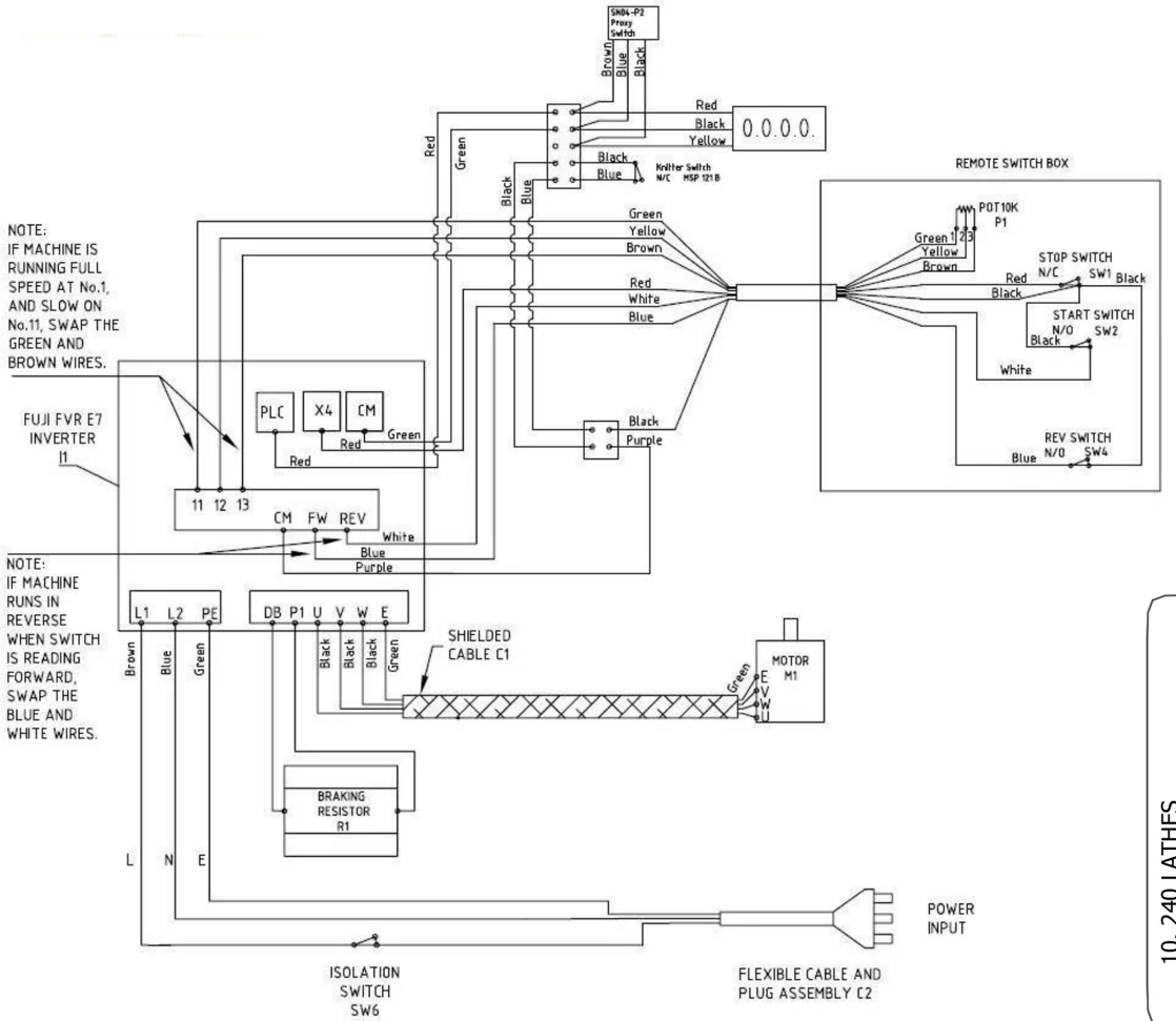
NOTE: IF MACHINE IS RUNNING FULL SPEED AT No.1, AND SLOW ON No.11, SWAP THE GREEN AND BROWN WIRES.
FUJI FVR E7 INVERTER [1]
PLC X4 CM Red Green Red 11 12 13 CM FW REV White Blue Purple
NOTE: IF MACHINE RUNS IN REVERSE WHEN SWITCH IS READING FORWARD, SWAP THE BLUE AND WHITE WIRES.
L1 L2 PE DB P1 U V W E Brown Blue Green Black Black Black Green
SHIELDED CABLE C1
MOTOR M1
BRAKING RESISTOR R1
L N E
ISOLATION SWITCH SW6
REMOTE SWITCH BOX
POT10K P1 Green Yellow Brown STOP SWITCH N/C SW1 Black Red Black START SWITCH N/O SW2 Black White REV SWITCH N/O SW4 Blue
POWER INPUT
FLEXIBLE CABLE AND PLUG ASSEMBLY C2
11. VL200/VL300 LATHES
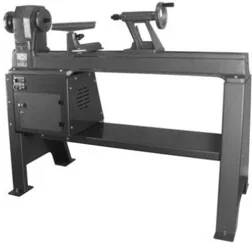
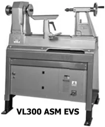
Lathe Models VL200, VL300 are equipped with the same headstock spindle, tailstock spindle, handwheels, handbrake wheels and bearings. Therefore all adjustments and assembly methods on the headstock and the tailstock on those models are the same. The Camlock assemblies are of the same system but different sizes.
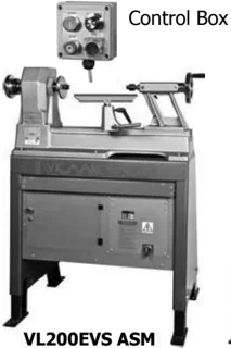
11.1 Spindle Pulley Speeds
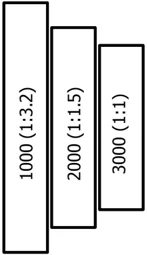
It is important that the belt is on the right pulley for the speed required. Not doing so can cause the motor to overheat. Below is a representation of the headstock pulleys and their equivalent ratio’s.
Maximum Speed for the 3 step pulley
| Pulley Ratio | |||
|---|---|---|---|
| Readout | 1:1 | 1:1.5 | 1:3.2 |
| 3000 | 3000 | 2040 | 938 |
| 2500 | 2500 | 1667 | 781 |
| 2000 | 2000 | 1333 | 625 |
| 1500 | 1500 | 1000 | 469 |
| 1000 | 1000 | 667 | 312 |
| 500 | 500 | 333 | 156 |
| 250 | 250 | 167 | 78 |
| 100 | 100 | 67 | 32 |
| 30 | 30 | 20 | 10 |
11.2 VL200/300 Exploded Views - Tailstock
| VL200/300 Tailstock | ||||
|---|---|---|---|---|
| Number | Qty | VL200 Part No. | VL300 Part No | Description |
| 1 | 1 | P00326 | P00326 | Revolving Handle, M8 |
| 2 | 3 | P00745 | P00745 | Socket Set Screw, M8 x 12 |
| 3 | 1 | V00451 | V00451 | Handwheel |
| 4 | 1 | Tailstock Bush | ||
| 5 | 1 | Brass Washer For Tailstock | ||
| 6 | 1 | V01051 | V01051 | Tailstock Spindle |
| 7 | 1 | V00957 | V00957 | Quill |
| 8 | 1 | P00401 | P00401 | Adjustable Handle, M10 x 20 |
| 9 | 1 | Brass Piece For Tailstock | ||
| 10 | 1 | V00270 | V00270 | Live Centre, Cup |
| 11 | 1 | V00803 | V00803 | Tailstock Lever |
| 12 | 1 | V00309 | V00309 | Tailstock Clamping Pin |
| 13 | 1 | V00906 | V00906 | Clamping Plate, 62mm |
| 14 | 1 | P00511 | P00511 | Hex Nut, M12 |
| 15 | 1 | P00241 | P00241 | Circlip, External 11mm |
| 16 | 1 | V00235 | V00236 | Tailstock |
| 17 | 1 | V00712 | V00712 | Tailstock Quill Key |

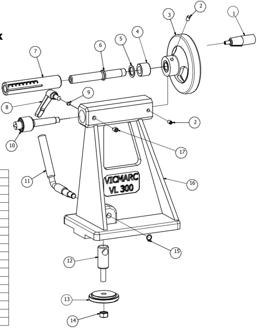

11. VL200/300 LATHES
11.2 VL200/300 Exploded Views - Camlock
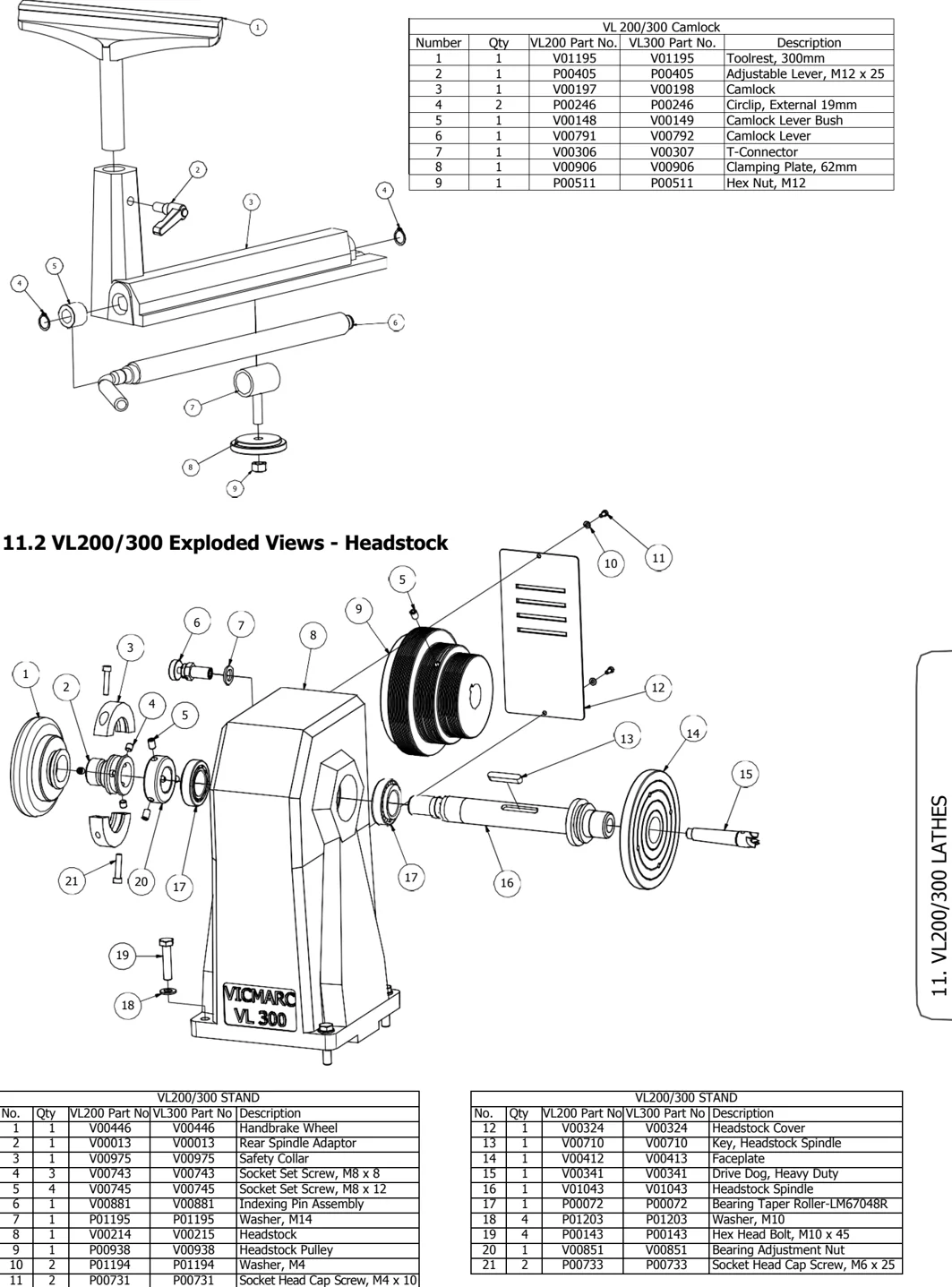
| VL 200/300 Camlock | ||||
|---|---|---|---|---|
| Number | Qty | VL200 Part No. | VL300 Part No. | Description |
| 1 | 1 | V01195 | V01195 | Toolrest, 300mm |
| 2 | 1 | P00405 | P00405 | Adjustable Lever, M12 x 25 |
| 3 | 1 | V00197 | V00198 | Camlock |
| 4 | 2 | P00246 | P00246 | Circlip, External 19mm |
| 5 | 1 | V00148 | V00149 | Camlock Lever Bush |
| 6 | 1 | V00791 | V00792 | Camlock Lever |
| 7 | 1 | V00306 | V00307 | T-Connector |
| 8 | 1 | V00906 | V00906 | Clamping Plate, 62mm |
| 9 | 1 | P00511 | P00511 | Hex Nut, M12 |
11.2 VL200/300 Exploded Views - Headstock
| VL200/300 STAND | ||||
|---|---|---|---|---|
| No. | Qty | VL200 Part No | VL300 Part No | Description |
| 1 | 1 | V00446 | V00446 | Handbrake Wheel |
| 2 | 1 | V00013 | V00013 | Rear Spindle Adaptor |
| 3 | 1 | V00975 | V00975 | Safety Collar |
| 4 | 3 | V00743 | V00743 | Socket Set Screw, M8 x 8 |
| 5 | 4 | V00745 | V00745 | Socket Set Screw, M8 x 12 |
| 6 | 1 | V00881 | V00881 | Indexing Pin Assembly |
| 7 | 1 | P01195 | P01195 | Washer, M14 |
| 8 | 1 | V00214 | V00215 | Headstock |
| 9 | 1 | P00938 | V00938 | Headstock Pulley |
| 10 | 2 | P01194 | P01194 | Washer, M4 |
| 11 | 2 | P00731 | P00731 | Socket Head Cap Screw, M4 x 10 |
| VL200/300 STAND | ||||
|---|---|---|---|---|
| No. | Qty | VL200 Part No | VL300 Part No | Description |
| 12 | 1 | V00324 | V00324 | Headstock Cover |
| 13 | 1 | V00710 | V00710 | Key, Headstock Spindle |
| 14 | 1 | V00412 | V00413 | Faceplate |
| 15 | 1 | V00341 | V00341 | Drive Dog, Heavy Duty |
| 16 | 1 | V01043 | V01043 | Headstock Spindle |
| 17 | 1 | P00072 | P00072 | Bearing Taper Roller-LM67048R |
| 18 | 4 | P01203 | P01203 | Washer, M10 |
| 19 | 4 | P00143 | P00143 | Hex Head Bolt, M10 x 45 |
| 20 | 1 | V00851 | V00851 | Bearing Adjustment Nut |
| 21 | 2 | P00733 | P00733 | Socket Head Cap Screw, M6 x 25 |
11. VL200/300 LATHES
11.2 VL200/VL300 LATHE Exploded Views - Stand
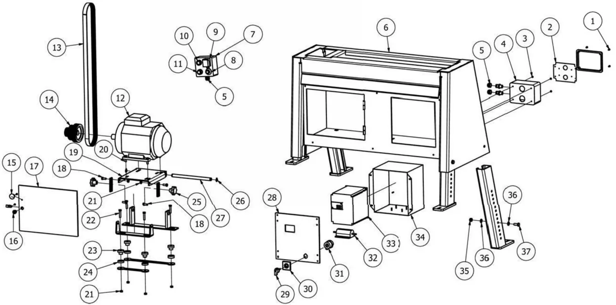
VL200/300 STAND
| Number | Qty | VL200 Part No. | VL300 Part No | Description |
|---|---|---|---|---|
| 1 | 4 | Junction Box Screws | ||
| 2 | 1 | Electrical Box Inner Plate | ||
| 3 | 4 | P00701 | P00701 | Pan Head Screw, M5 x 20 |
| 4 | 1 | Junction Box | ||
| 5 | 3 | P00210 | P00210 | Cable Gland, 16mm |
| 6 | 1 | - | - | Stand Assembly |
| 7 | 1 | P00180 | P00180 | Remote Switch Box |
| 8 | 1 | P00631 | P00631 | Speed Controller |
| 9 | 1 | P00642 | P00642 | Reverse Button |
| 10 | 1 | P00641 | P00641 | Start Button |
| 11 | 1 | P00640 | P00640 | Stop Button |
| 12 | 1 | P00465 | P00466 | Motor |
| 13 | 1 | P00090 | P00091 | Belt Poly V - J10-690 |
| 14 | 1 | V00939 | V00939 | Motor Pulley |
| 15 | 1 | Motor Door Knob | ||
| 16 | 1 | Motor Door Latch | ||
| 17 | 1 | - | - | Motor Door |
| 18 | 4 | P00130 | P00130 | Bolt, M8 x 20 |
VL200/300 STAND
| Number | Qty | VL200 Part No. | VL300 Part No | Description |
|---|---|---|---|---|
| 19 | 1 | - | - | Motor Mount Plate |
| 20 | 4 | P00133 | P00133 | Bolt, M8 x 30 |
| 21 | 6 | P00509 | P00509 | Nut, M8 |
| 22 | 4 | P00135 | P00135 | Bolt, M8 x 45 |
| 23 | 4 | V00846 | V00846 | Motor mount Bush, Male |
| 24 | 4 | V00845 | V00845 | Motor mount Bush, Female |
| 25 | 2 | P00351 | P00351 | Star Knob Female, M8 |
| 26 | 2 | P00244 | P00244 | External Circlip, 16mm |
| 27 | 1 | - | - | Motor mount Shaft |
| 28 | 1 | - | - | Inverter Door |
| 29,30 & 31 | 1 | P01111 | P01111 | Main Switch Assembly |
| 32 | 1 | P00650 | P00650 | Breaking Resistor |
| 33 | 1 | P00346 | P00343 | Inverter |
| 34 | 1 | P00195 | P00195 | Electronic Box |
| 35 | 4 | P00518 | P00518 | Nylock Nut, M10 |
| 36 | 8 | P01203 | P01203 | Washer, M10 |
| 37 | 4 | P00157 | P00157 | Bolt, M10 x 25 |
11. VL200/300 LATHES
11.2 VL200/300 Exploded Views - Wiring Diagram 6 Speed
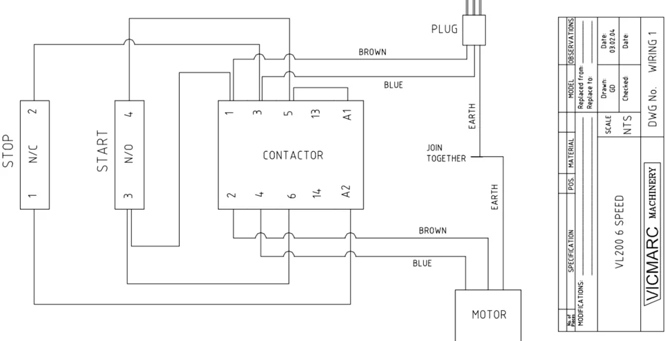
11.2 VL200/300 Exploded Views - Wiring Diagram
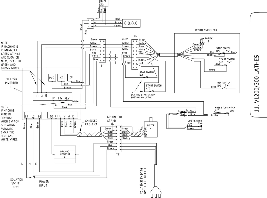
12. VL200/VL240/VL300 LATHES
12.1 Setting up The Tailstock
The eccentric locking mechanism of the tailstock is factory preset. If adjusting is necessary the following steps are applicable.
- Slide tailstock to the end of the bed as illustrated.
- Undo the M12 locking nut (anticlockwise is tightening and clockwise is loosening) with an 18mm open end spanner, then rotate the clamping plate clockwise to tighten.
- Lock the Tail stock with locking lever, if lever is in the correct position is at eleven o'clock Re-lock the locking nut.
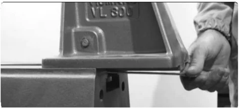
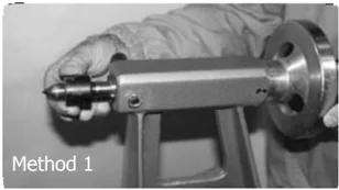
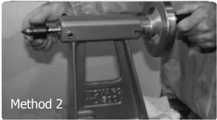
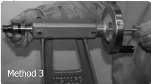
12.2 Ejecting the Morse Taper
The taper can be ejected a few ways depending on which is applicable
- Quickly turn and pull the taper out.
- Turn the hand wheel anti-clockwise until the taper is ejected.
- When the MT2 taper is shorter than the standard taper they must be knocked out using the knock out bar supplied. Lightly tap the bar while holding the taper (to prevent the taper from falling to the ground).
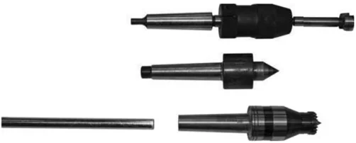
Method 1 Method 2 Method 3
12.3 Servicing the Tailstock
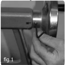
Removing the Quill on the Tailstock
- Lock the tailstock onto the bed using the locking lever.
- Turn the hand wheel so that 20-25mm of the quill is protruding from the front of thetailstock.
- Loosen the grub screws on the handwheel two or three revolutions.
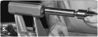
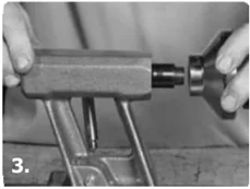
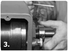
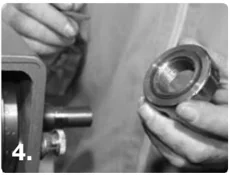
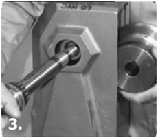
- Using a rubber hammer, tap off the hand wheel.
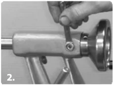
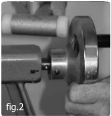
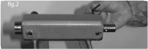
- Loosen the two grub screws at the rear end of the tailstock two revolutions.
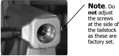
- Note. Do not adjust the screws at the side of the tailstock as these are factory set. (Quill keyway will be damaged if these screws are adjusted)
- Mark the quill to ensure that it is replaced exactly as it was prior to removal.
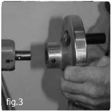
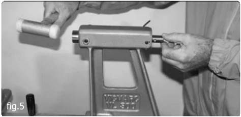
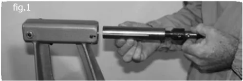
- Lightly tap the front of the quill with a rubber mallet as show in fig. 3.
- The quill can now be cleaned along with the inside of the tailstock.
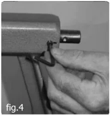
- Note. Never use sandpaper to clean the quill and take care not to remove the brass cylinder at the end of the locking lever while cleaning.
- All mobile parts should now be greased with a high quality grease or graphite grease before re-assembly.
Note. Do not adjust the screws at the side of the tailstock as these are factory set.
fig.5
VIOMARC LATHES P24

12. VL200/240/300 LATHES
Re-Assembling the Quill on the Tailstock:
- The quill should be re-placed from the back of the tailstock making sure that it is horizontal to the bore.
- Push the quill back into place and align with the markings that were made beforeremoval.
- Alternately tighten the two grub screws that hold the quill in place (do not over tighten).
- Replace the hand wheel and tighten thegrubs crews.
- Turn the hand wheel. If it doesn't run smoothly (i.e. slight gripping or scraping) several light taps on the hand wheel with rubber hammer will bring the quill into alignment.
- The free play of the hand wheel should be no more than 10 degrees.
12.4 Setting up The Camlock
The eccentric locking mechanism of the Camlock is factory preset. If adjusting it is necessary the following steps are applicable.
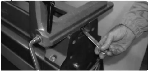
- Remove Tailstock than slide Camlock to the end of the bed as illustrated.
- Undo the M12 locking nut (anticlockwise is tightening and clockwise is loosening) with an 18mm open end spanner, then rotate the clamping plate clockwise to tighten.
- Lock the Camlock with locking lever, if lever is in the correct position is at four or eight o clock, relock the locking nut. (Camlock is designed to lock in both directions).
12.5 Servicing the Camlock
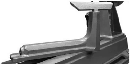
- Undo the two circlips(one on the lever side one on the rear).
- Reach underneath and support the clamping plate.
- Slide out the Camlock bar.
- Thoroughly clean the shaft and the bore.
- Re-grease the shaft with a high quality bearing grease.
- To re-assemble, slide in the shaft through the boreand the Camlock T-Connector.
- Replace the circlips.
12.6 Setting up the Safety Ring
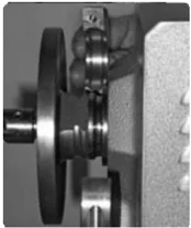
When using the lathe in reverse use safety rings to prevent the workpiece from unscrewing itself off the lathe. The following step is applicable when relocating the safety ring.
- Remove safety ring from outboard side of the headstock with 5 mm Allen key provided and re-install the safety ring on the inboard side of the Headstock as shown.
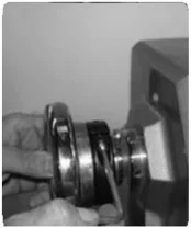
12.7 Changing the Belt Ratio
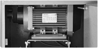
Depending on the size of the work piece to be turned (see Turning Diameter and Turning Speeds Page 6) the belt ratio may require changing for different speeds.
- Before commencing any maintenance work with the machine, make sure that the mains switch is in the off position.
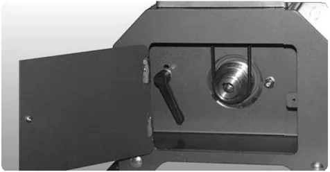
- Open the motor door at the front of the lathe.
- Loosen the two star knobs on either side of the motor cradle.
- Move the motor slightly upwards to loosen the belt and tighten one of the star knobs to hold it in place.
- Once loosened seat the belt precisely on the correct pulley ratio.
- Loosen the star knob to allow the motor to drop down then retighten both star knobs.
- Check the tension of the belt. It should have a maximum deflection of 10-15mm (do not over tighten as it can cause motor bearing problems) see page 17.
- Close the front door. (The front door has a limit switch so the machine will not start if left open)
www.vicmarc.com P25

12. VL200/240/300 LATHES
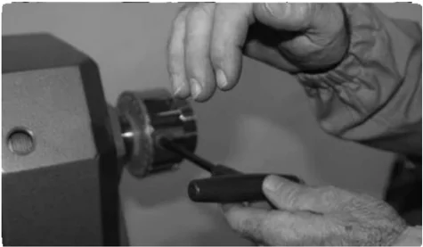
12.8 Mounting and Removing the Chuck
Mounting Before mounting the chuck, make sure that the threads are clean and free of grit.
- To mount the chuck on the lathe, carefully place the chuck on the thread with your right hand, making sure it is square.
- Turn the hand wheel slowly with your left hand to screw on the chuck until it is tight.
- The machine should never be turned on for this procedure.
- If the chuck is too heavy for this procedure then the indexing pin should be engaged and the chuck slowly turned with both hands until it is tight.
Removing
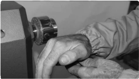
- To release the chuck first ensure that the safety ring has been removed and engage the indexing pin.
- Place the Allen key into the chuck.
- Use a light tap with the hand or a soft mallet (never use a metal one) to unbind the thread.
- Remove the Allen key and unwind the chuck using the hand wheel.
- Tip: If you have continued problems removing the chuck, a thin PVC (nylon) washer can be between the face of the chuck and the face of the spindle before the chuck is screwed on. This prevents metal to metal binding which can make it difficult to remove the chuck.
12.9 Outboard Turning Set Up
For outboard turning, the handbrake wheel needs to be removed - to do so:
- Remove the safety ring.
- Engage the indexing pin.
- Loosen the handbrake wheel in an anticlockwise direction using the spanner provided then unscrew the handbrake wheel.
- Screw the handbrake wheel onto the opposite (inboard) side of the lathe and tighten with the spanner provided.
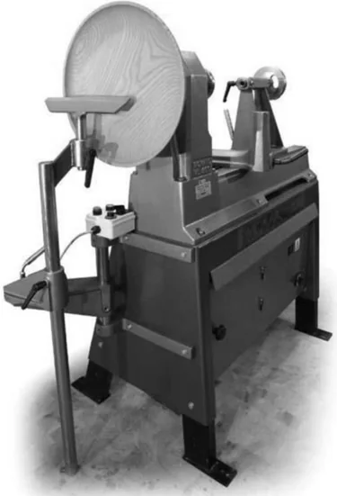
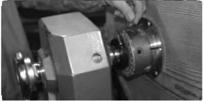
Important Note Before all outboard turning ensure that the 3 steps (below) have been completed.
Step 1. Before turning large pieces it is recommended to put the ratio 1:3
 Step 2. Clamp the workpiece
 Step 3. Mount the Safety Ring
VIOMARC LATHES P26

12. VL200/240/300 LATHES
12.10 Replacing the Belt
VL200, VL240, VL300
All Vicmarc® lathes are factory installed with high quality belts, which give many years of service before requiring replacement.
Removing the Belt:
- Make sure that the lathe is turned off at the mains switch.
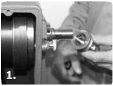
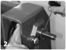
- Remove safety ring.
- Measure the distance between the largest pulley and the inside of the headstock so that the pulley can be re-installed at the exact same original position.
- Loosen the belt as per changing the belt ratio.
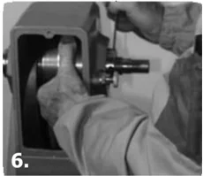
- Loosen the grub screws on the rear spindle adaptor.
- Engage the indexing pin and unscrew the handbrake wheel anti-clockwise and remove.
- Loosen the three grub screws in the thrust ring and remove.
- Loosen the grub screws on the headstock pulley with a 4mm Allen key.
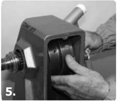
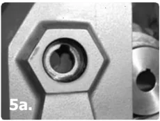
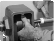
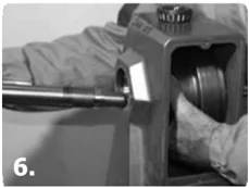
- From the hand wheel side, lightly tap the spindle with a rubber mallet (or nylon hammer) making sure that it stays horizontal. It is important to make sure that the spindle keyway is in the vertical position so that it can pass through the keyway opening. (see picture 5).
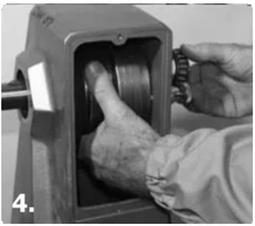
- Ensure that the taper roller bearing on the handbrake wheel side does not fall out.
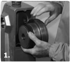
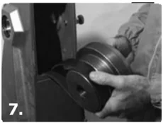
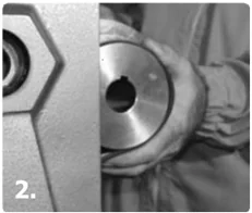
- Remove the spindle ensuring that the pulleys are not allowed to drop (caution the pulleys are cast iron and are heavy).
- Place the spindle in a clean place and pull out the pulley wheels.
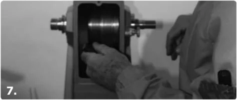
- The belt can now be removed, making way for a new belt.
Re-Assembly
- Sit the new belt on the pulley & place back into headstock.
- When re-inserting the spindle, make sure that the key on the spindle lines up with the keyway to avoid any damage.
- Line up the pulley back in its original position and re-tighten the grub screws in the middle pulley.
- Screw the thrust ring back on until there is no axial play in the spindle and tighten the grub screws.
- Screw the handbrake wheel back on.
- Hook belt around the motor pulley and tighten the belt adjustment. Check the belt deflection to ensure the correct tension. (see page 17)
- Once assembled replace all covers, disengage the indexing pin and turn spindle by the hand wheel to check for hard spots.
- Turn the machine on at the mains switch and run the machine at moderate Rpm (approx. 1500 rpm) for five minutes to check the operation of the machine.
- If the pulley housing gets hotter than luke warm to touch after 5 minutes of operation then stop the machine, loosen the thrust ring grub screws and unscrew the thrust ring approx. 2 to 5 degrees then re-tighten the grub screws.
www.vicmarc.com P27

13. TROUBLESHOOTING
| Problem | Solution |
|---|---|
| A knocking noise can be heard when the machine is running. | Wood splinters or some other foreign object has contaminated the pulleys or the V-belt. Turn off main switch and remove contaminants. Or A grub screw could have come loose on headstock pulley or motor pulley. Locate and retighten the grub screw. |
| The speed controller is not responding correctly. | The controller is dusty or there is some moisture build up. Turn off the machine and rotate the speed controller knob a few times or blow out with compressed air. |
| The machine will not turn on or start. | Make sure the red stop bar is pulled all the way out and isn't stuck in. Also make sure the doors are closed so that all the limit switches are activated. |
| Belt making screeching noise or jumping off the pulley. | Belt not in line, rubbing up against the face of the pulley. Re-align the belt making sure the motor pulley is in line and square with the headstock pulley. |
| RPM of the spindle is fluctuating. | Potentiometer could be faulty and should be replaced. Or The electrical unit functions have been altered. |
| Machine is vibrating. | The machine may be resting on two or three points on the feet causing the machine to oscillate. Re-level the machine so all four feet are supporting the machine pack the feet if necessary to keep level. |
| The headstock and tailstock are not in alignment. | If your machine is bolted down make sure the floor is level as uneven ground can cause the bed to twist thus putting the headstock and tailstock out of alignment. Or The tailstock or the live center is not sitting level on the bed. Remove the tailstock and make sure the bed slides are clean. Then remove the live centre and wipe down to remove any debris from the Morse taper. |
| The electronic unit overloads when slowing down the speed on the lathe or stopping the lathe. | When turning large work pieces and you slow down too fast or stop the lathe, the electrical unit tries to slow down the piece of wood. The momentum of the wood generates power, which feeds back into the inverter. If too much power is generated then it gets past the breaking resistor and can cause the unit to overload. Try slowing down the lathe at a slower rate then stopping the lathe at a slower speed to help stop it from overloading. |
| Tailstock spindle seizing up when drilling through the centre with Auger. | Retract the quill as far back as possible. This preventing saw dust from entering the spindle. To clear the sawdust, blow out with compressed air. |
Symptoms of Loose or Broken Wiring
| Problem | Solution |
|---|---|
| Will not start or intermittent start. Once started will maintain direction. | White Wiring broken/loose. |
| No Reverse starting. However, if starting has occurred, reverse will be maintained until stop command is given. | Blue Wiring broken/loose. |
| Will not start unless green button is continually pressed. Also intermittent stopping for no reason. | Red Wiring broken/loose. |
| Will make lathe stop. If wiring is loose, re-start may be possible. This symptom can be erratic or intermittent. | Black Wiring broken/loose. |
| Lathe will accelerate to 30rpm and stay there. If connection is loose, speed will fluctuate between set speed and 30rpm. | Yellow Wiring broken/loose. |
| Lathe will accelerate from set speed to maximum speed 3000rpm. If connection is loose, speed will fluctuate or be erratic between set speed and 3000rpm (Max). | Green Wiring broken/loose |
VIGMARC LATHES P28

14. LATHE SPECIFICATIONS

| Model | Center Height | Swing over Bed" | Distance Between Centres" | Work Height | Indexing Holes" | Spindle Taper | Spindle Bearings | Spindle RPM | Motor kW | RPM Digital Readout | Toolrest Post Diameter | Hole Through Headstock Spindle | Hole Through Tailstock Spindle | Quill Travel |
|---|---|---|---|---|---|---|---|---|---|---|---|---|---|---|
| VL150 BM | 152mm | 304mm | 350mm | - | 24 | MT2 | Tapered Roller | 6 Speed | - | - | 25.4mm | 10.5mm | 10.5mm | 65mm |
| VL150 SM | 152mm | 304mm | 350mm | - | 24 | MT2 | Tapered Roller | EVS 30-3000 | 0.75 | Inverter Only | 25.4mm | 10.5mm | 10.5mm | 65mm |
| VL200 BM Short | 200mm | 400mm | 400mm | - | 24 | MT2 | Tapered Roller | 6 Speed | - | - | 30mm | 15mm | 10.5mm | 75mm |
| VL200 BM Long | 200mm | 400mm | 1000mm | - | 24 | MT2 | Tapered Roller | 6 Speed | - | - | 30mm | 15mm | 10.5mm | 75mm |
| VL200 SM 6SP | 200mm | 400mm | 1000mm | 1140mm | 24 | MT2 | Tapered Roller | 6 Speed | 0.75 | Inverter Only | 30mm | 15mm | 10.5mm | 75mm |
| VL200 SM EVS | 200mm | 400mm | 1000mm | 1140mm | 24 | MT2 | Tapered Roller | EVS 30-3000 | 1.5 | Inverter Only | 30mm | 15mm | 10.5mm | 75mm |
| VL200 ASM Short | 200mm | 400mm | 400mm | 940 - 1240mm | 24 | MT2 | Tapered Roller | EVS 30-3000 | 1.5 | Inverter Only | 30mm | 15mm | 10.5mm | 75mm |
| VL200 ASM Long | 200mm | 400mm | 1000mm | 940 - 1240mm | 24 | MT2 | Tapered Roller | EVS 30-3000 | 1.5 | Inverter Only | 30mm | 15mm | 10.5mm | 75mm |
| VL240 BM | 245mm | 490mm | 500mm | - | 24 | MT2 | Tapered Roller | EVS 30-3000 | 1.5 | Spindle RPM | 30mm | 15mm | 10.5mm | 75mm |
| VL240 ASM | 245mm | 490mm | 500mm | 1020 - 1200mm | 24 | MT2 | Tapered Roller | EVS 30-3000 | 1.5 | Spindle RPM | 30mm | 15mm | 10.5mm | 75mm |
| VL300 BM EVS | 302mm | 604mm | 500mm | 24 | MT2 | Tapered Roller | 3 Speed | - | - | 30mm | 15mm | 10.5mm | 75mm | |
| VL300 SM EVS | 302mm | 604mm | 500mm | 1136mm | 24 | MT2 | Tapered Roller | EVS 30-3000 | 1.5 | Spindle RPM | 30mm | 15mm | 10.5mm | 75mm |
| VL300 ASM | 302mm | 604mm | 500mm | 1060 - 1360mm | 24 | MT2 | Tapered Roller | EVS 30-3000 | 2.2 | Spindle RPM | 30mm | 15mm | 10.5mm | 75mm |
15. TECHNICAL INFORMATION
MOTOR INFORMATION
| Lathe Model | Power (kW) | RPM | Freq (Hz) | Volts (V) | Amps | Vicmarc® Re-Order Code |
|---|---|---|---|---|---|---|
| VL150 BM | No Motor Included - Motor Pulley Hole Diameter 14mm / 5/8" / 19mm | |||||
| VL150 SM | 0.75 | 1410 | 50 | 280-420 | 1.5 | P00462 |
| VL200 BM | No Motor Included - Motor Pulley Hole Diameter 5/8" / 19mm | |||||
| VL200 6SP | 0.75 | 1415 | 50 | 240 | 5.8 | P00461 |
| VL200L ASM & VL200 SM | 1.5 | 1445 | 50 | 280-420 | 3.3 | P00465 |
| VL200S ASM & VL200 Sit Down | 1.5 | 1445 | 50 | 280-420 | 3.3 | P00465 |
| VL240 | 1.5 | 1450 | 50 | 280-420 | 3.3 | - |
| VL300BM | No Motor Included - Motor Pulley Hole Diameter 28mm | |||||
| VL300S SM | 1.5 | 1445 | 50 | 280-420 | 3.3 | P00465 |
| VL300S ASM | 2.2 | 1460 | 50 | 280-420 | 4.8 | P00466 |
BELT INFORMATION
| Lathe Model | Type | Section | Ribs | Length (mm) | Vicmarc® Re-Order Code |
|---|---|---|---|---|---|
| VL150 BM | Poly-V Belt | J | 3 | 380 | - |
| VL150 SM | Poly-V Belt | J | 5 | 380 | P00084 |
| VL200BM | Poly-V Belt | J | 6 | 610 | P00088 |
| VL200 6SP | Poly-V Belt | J | 6 | 550 | - |
| VL200L ASM | Poly-V Belt | J | 10 | 610 | P00090 |
| VL200S ASM | Poly-V Belt | J | 10 | 610 | P00090 |
| VL200L SM & VL200 Sit Down | Poly-V Belt | J | 10 | 550 | P00088 |
| VL240 | Poly-V Belt | J | 9 | 420 | - |
| VL300BM | Poly-V Belt | J | 10 | 690 | P00091 |
| VL300L ASM | Poly-V Belt | J | 10 | 690 | P00091 |
| VL300S SM | Poly-V Belt | J | 10 | 610 | P00090 |
| VL300S ASM | Poly-V Belt | J | 10 | 690 | P00091 |
HEADSTOCK BEARING SIZES
| Lathe Model | Inboard | Outboard | ||
|---|---|---|---|---|
| Bearing Number | Vicmarc® Re-order Code | Bearing Number | Vicmarc® Re-order Code | |
| VL150 BM | 32005 | P00071 | 32004 | P00070 |
| VL150 SM | 32005 | P00071 | 32004 | P00070 |
| VL200BM | LM67048 | P00072 | LM67048 | P00072 |
| VL200 6SP | LM67048 | P00072 | LM67048 | P00072 |
| VL200L ASM & SM | LM67048 | P00072 | LM67048 | P00072 |
| VL200S ASM & VL200 Sit Down | LM67048 | P00072 | LM67048 | P00072 |
| VL240 | LM67048 | P00072 | LM67048 | P00072 |
| VL300BM | LM67048 | P00072 | LM67048 | P00072 |
| VL300S SM | LM67048 | P00072 | LM67048 | P00072 |
| VL300S ASM | LM67048 | P00072 | LM67048 | P00072 |

VICMARC MACHINERY
PTY.LTD.
Manufacturers of Quality Woodturning Lathes, Chucks and Accessories
Phone (07)3284 3103 Fax (07)3283 4656 Int Ph. 61-7 3284 3103 Int Fax 61-7 3283 4656 Email: vicmarc@vicmarc.com Web www.vicmarc.com A: 52 Grice Street Clontarf QLD 4019 Australia
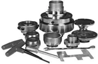
CHUCKS
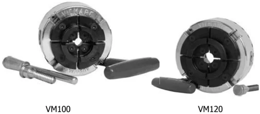
VM100 VM120 SCREW FACEPLATES ECCENTRIC CHUCK #3
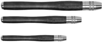
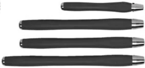
TURNING TOOLS & HANDLES
QUICK RELEASE TOOL HANDLES FIXED BORE HANDLES BOWL GOUGES
ACCESSORIES
VACUUM CUPS SHARK JAWS BOWL JAWS DRIVE DOGS THREE POINT STEADIES
SEE OUR FULL RANGE www.vicmarc.com
www.vicmarc.com P31



VICMARC® MACHINERY PTY. LTD.
Manufacturers of Quality Woodturning Lathes and Accessories
The Vicmarc® Warranty Policy
Vicmarc® Machinery Pty Ltd makes every effort to manufacture Vicmarc® products to a high quality standard, using the finest materials and up to date manufacturing methods. However, if a customer experiences problems with Vicmarc® Products, we must make every effort to remedy the problem.
In the first instance, distributors are responsible to manage warranty issues on behalf of Vicmarc® Machinery.
The warranty period for electronics, such as motors and units is 12 months. The warranty period for lathe parts, chucks and accessories is 5 years.
If within the warranty period the product fails due to faulty materials or workmanship, the distributor on behalf of Vicmarc® Machinery, will need to arrange for the repair or replacement of faulty items.
The warranty is subject to the following conditions:
- Vicmarc® will decline liability if the product has been modified in any way without written authorisation from Vicmarc® Machinery
- The warranty is void if the product shows signs of misuse or abnormal over-use i.e. daily heavy duty industrial use.
- The warranty is conditional on the product having been installed and used according to the instruction provided in the owner's manual.
- The product has not been subjected to misuse and or negligence.
- Faulty items will be replaced where possible with an identical item or a suitable substitute.
- Belts are excluded from warranty cover.
- The distributor should retain failed items, as Vicmarc® or suppliers to Vicmarc® may need them to investigate the cause of failure to initiate improvements.
- Any major replacement of parts and equipment under warranty, resulting in a claim against Vicmarc® Machinery, requires prior approval from Vicmarc® office before a replacement is agreed to.
Please note: At times, a judgement call by the distributor may be needed to determine whether there is a genuine case for a claim under warranty.
Lathe Model _________________________________ Serial Number _______________________________ Thread Size __________________________________ Electrical Unit Model ________________________ Year of Manufacture __________________________ Date Of Purchase _____________________________
 Manufactured in Australia by
VICMARC® MACHINERY
PTY. LTD.
A.B.N. 60 062 261 036 CE
20 YEAR VL300 1246 SERIAL NO.
Each Vicmarc® lathe has an identification plate stating the year of manufacture, model number and the serial number. Each Vicmarc® Lathe Model has been CE certified.
Distributed by:
within Australia 07 3284 3103 overseas +61 7 3284 3103 www.vicmarc.com