D6_Quilt _BrotherE_cover Pantone 285 K
brother®
Operation Manual 882-U60
Getting Ready Sewing Basics Utility Stitches Character/ Decorative Stitches My Custom Stitch Appendix
Computerized Sewing and Quilting Machine Operation Manual
English 882-U60 XE0783-001 Printed in Taiwan
IMPORTANT SAFETY INSTRUCTIONS
When using this machine, basic safety precautions should always be taken, including the following: Read all instructions before using.
DANGER - To reduce the risk of electric shock:
- The machine should never be left unattended while plugged in. Always unplug the machine from the electrical outlet immediately after using and before cleaning.
WARNING - To reduce the risk of burns, fire, electric shock, or injury to persons:
- Do not allow this machine to be used as a toy. Close attention is necessary when the machine is used by or near children.
- Use this machine only for its intended use as described in this manual. Use only accessories recommended by the manufacturer as contained in this manual.
- Never operate this machine if it has a damaged cord or plug, if it is not working properly, if it has been dropped or damaged, or dropped into water. Return the machine to the nearest authorized dealer or service center for examination, repair, electrical or mechanical adjustment.
- Never operate the machine with any air openings blocked. Keep ventilation openings of the machine and foot control free from the accumulation of lint, dust, and loose cloth.
- Never drop or insert any object into any opening.
- Do not use outdoors.
- Do not operate where aerosol (spray) products are being used or where oxygen is being administered.
- To disconnect, turn the main switch to the symbol “○” position which represents off, then remove plug from outlet.
- Do not unplug by pulling on cord. To unplug, grasp the plug, not the cord.
- Keep fingers away from all moving parts. Special care is required around the machine needle.
- Always use the proper needle plate. The wrong plate can cause the needle to break.
- Do not use bent needles.
- Do not pull or push fabric while stitching. It may deflect the needle causing it to break.
- Switch the machine to the symbol “○” position when making any adjustments in the needle area, such as threading needle, changing needle, threading bobbin, or changing presser foot, and the like.
- Always unplug the machine from the electrical outlet when removing covers, lubricating, or when making any other user servicing adjustments mentioned in the instruction manual.
- This sewing machine is not intended for use by young children or infirm persons without supervision.
- Young children should be supervised to ensure that they do not play with this machine.
- If the LED light unit (light-emitting diode) is damaged, it must be replaced by authorized dealer.
SAVE THESE INSTRUCTIONS This machine is intended for household use.
FOR USERS IN THE UK, EIRE, MALTA AND CYPRUS ONLY
If this machine is fitted with a three-pin non-rewireable BS plug then please read the following.
I MPORTANT
If the available socket outlet is not suitable for the plug supplied with this equipment, it should be cut off and an appropriate three-pin plug fitted. With alternative plugs an approved fuse must be fitted in the plug.
NOTE
The plug served from the main lead must be destroyed as a plug with bared flexible cords is hazardous if engaged in a live socket outlet. In the event of replacing the plug fuse, use a fuse approved by ASTA to BS 1362, i.e. carrying the mark, rating as marked on plug. Always replace the fuse cover, never use plugs with the fuse cover omitted.
WARNING
DO NOT CONNECT EITHER WIRE TO THE EARTH TERMINAL WHICH IS MARKED WITH THE LETTER 'E', BY THE EARTH SYMBOL ⏚ OR COLOURED GREEN OR GREEN AND YELLOW.
The wires in this main lead are coloured in accordance with the following code:
Blue Neutral
Brown Live
As the colours of the wiring in the main lead of this appliance may not correspond with the coloured markings identifying the terminals in your plug, proceed as follows.
The wire which is coloured blue must be connected to the terminal which is marked with the letter 'N' or coloured black or blue.
The wire which is coloured brown must be connected to the terminal which is marked with the letter 'L' or coloured red or brown.
Federal Communications Commission (FCC)
Declaration of Conformity (For USA Only)
Responsible Party: Brother International Corporation 100 Somerset Corporate Boulevard Bridgewater, NJ 08807-0911 USA TEL : (908) 704-1700
declares that the product
Product Name: Brother Sewing Machine Model Number: QC-1000
This device complies with Part 15 of the FCC Rules. Operation is subject to the following two conditions: (1) this device may not cause harmful interference, and (2) this device must accept any interference received, including interference that may cause undesired operation.
This equipment has been tested and found to comply with the limits for a Class B digital device, pursuant to Part 15 of the FCC Rules. These limits are designed to provide reasonable protection against harmful interference in a residential installation. This equipment generates, uses, and can radiate radio frequency energy and, if not installed and used in accordance with the instructions, may cause harmful interference to radio communications. However, there is no guarantee that interference will not occur in a particular installation. If this equipment does cause harmful interference to radio or television reception, which can be determined by turning the equipment off and on, the user is encouraged to try to correct the interference by one or more of the following measures:
- Reorient or relocate the receiving antenna
- Increase the separation between the equipment and receiver.
- Connect the equipment into an outlet on a circuit different from that to which the receiver is connected.
- Consult the dealer or an experienced radio/TV technician for help.
- The included interface cable should be used in order to ensure compliance with the limits for a Class B digital device.
- Changes or modifications not expressly approved by Brother Industries, Ltd. could void the user's authority to operate the equipment.
3
CONGRATULATIONS ON CHOOSING
OUR MACHINE
Your machine is the most advanced computerized household sewing machine. To fully enjoy all the features incorporated, we suggest that you study the manual.
PLEASE READ BEFORE USING THIS MACHINE
For safe operation
- Be sure to keep your eye on the needle while sewing. Do not touch the handwheel, thread take-up lever, needle, or other moving parts.
- Remember to turn off the power switch and unplug the cord when:
- Operation is completed
- Replacing or removing the needle or any other parts
- A power failure occurs during use
- Maintaining the machine
- Leaving the machine unattended.
- Do not store anything on the foot controller.
- Plug the machine directly into the wall. Do not use extension cords.
- Do not place or store the machine near heaters or other hot appliances, in any location exposed to extremely high or low temperatures, high humidity or dusty locations. Doing so could cause the machine to malfunction.
- Never operate the machine if it has a damaged cord or plug, if it is not working properly, if it has been dropped or damaged, or water is spilled on the unit. Return the machine to the nearest authorized dealer or service center for examination, repair, electrical or mechanical adjustment.
For a longer service life
- When storing this machine, avoid direct sunlight and high humidity locations. Do not use or store the machine near a space heater, iron, halogen lamp, or other hot objects.
- Use only neutral soaps or detergents to clean the case. Benzene, thinner, and scouring powders can damage the machine, and should never be used.
- Do not drop or hit the machine.
- Always consult the operation manual when replacing or installing any assemblies, the presser feet, needle, or other parts to assure correct installation.
- Use only the interface cable (USB cable) included with this machine.
For repair or adjustment
In the event a malfunction occurs or adjustment is required, first follow the troubleshooting table in the back of the operation manual to inspect and adjust the machine yourself. If the problem persists, please consult your local authorized Brother dealer.
For additional product information and updates, visit our web site at www.brother.com
The contents of this manual and specifications of this product are subject to change without notice.
4
HOW TO USE THIS MANUAL
Chapters 1 and 2 describe to the first-time user the initial operations for using this machine and the basic sewing operations.
To sew utility stitches
Continue with chapter 3 to learn how to select a stitch and sew using the various stitches.
To sew characters and patterns
Continue with chapter 4 to learn basic operations, from selecting patterns to sewing, in addition to operations such as combining and editing patterns to rotate or resize them, and storing combined patterns.
-
Parts related to operations described in the procedures are highlighted in blue. Perform the operations while comparing the screens in the procedures with those that appear on the machine.
-
If, while using the machine, you have questions about an operation or you would like to know more about a specific function, refer to the index (P.159) and the table of contents to find the section of the manual to refer to.
CONTENTS
- NAMES OF MACHINE PARTS AND THEIR FUNCTIONS ........ 9
- Machine ........ 9
- Needle and Presser Foot Section ........ 10
- Operation Buttons ........ 11
- Included Accessories ........ 11
- Options ........ 16
Chapter 1 Getting Ready 17
- TURNING THE MACHINE ON/OFF ........ 18
- LCD SCREEN ........ 19
- Using the Machine Setting Mode Key ........ 22
- Using the Machine Operation Mode Key ........ 23
- Using the Pattern Explanation Key ........ 24
- LOWER/UPPER THREADING ........ 25
- Winding the Bobbin ........ 25
- Setting the Bobbin ........ 28
- Pulling Up the Bobbin Thread ........ 28
- Upper Threading ........ 29
- Using the Twin Needle ........ 32
- CHANGING THE PRESSER FOOT ........ 34
- Removing the Presser Foot ........ 34
- Attaching the Presser Foot ........ 34
- CHANGING THE NEEDLE ........ 35
- SEWING LARGE PIECES OF FABRIC ........ 38
Chapter 2 Sewing Basics 39
- SEWING ........ 40
- Sewing a Stitch ........ 40
- Sewing Reinforcement Stitches ........ 42
- Sewing Curves ........ 42
- Changing Sewing Direction ........ 43
- Sewing Heavyweight Fabric ........ 43
- Sewing Lightweight Fabric ........ 43
- ADJUSTING STITCH SETTINGS ........ 44
- Adjusting the Stitch Width ........ 44
- Adjusting the Stitch Length ........ 44
- Adjusting the Thread Tension ........ 45
- USEFUL FUNCTIONS ........ 45
- Automatic Reinforcement Stitching ........ 45
- Automatic Thread Cutting ........ 46
- Pivoting ........ 47
- Automatic Fabric Sensor System ........ 48
- Locking the Screen ........ 49
Chapter 3 Utility Stitches 51
- SELECTING A UTILITY STITCH ........ 52
- Selecting a Stitch ........ 53
- Saving Stitch Settings ........ 53
- Using the Sewing Type Selection Key ........ 54
- SEWING THE STITCHES ........ 56
- Quilting ........ 56
- Straight Stitches ........ 66
- Darts Seams ........ 69
- Gathering ........ 70
- Flat Fell Seams ........ 70
- Pintucks ........ 71
- Zigzag Stitches ........ 72
- Elastic Zigzag Stitches ........ 74
- Overcasting ........ 75
- Blind Hem Stitches ........ 79
- Appliqués ........ 80
- Shell Tuck Stitching ........ 81
- Scalloping ........ 81
- Top Stitching ........ 82
- Smocking ........ 82
- Fagoting ........ 83
- Tape or Elastic Attaching ........ 84
- Heirloom Stitching ........ 85
- Buttonhole Stitches ........ 87
- Bar Tacks ........ 92
- Button Sewing ........ 94
- Eyelets ........ 95
- Multi-Directional Sewing (Straight Stitch and Zigzag Stitch) ........ 96
- Zipper Insertion ........ 97
Chapter 4 Character/Decorative Stitches 101
- SELECTING STITCH PATTERNS ........ 102 Selecting Decorative Stitch Patterns/ 7 mm Decorative Stitch Patterns/ Satin Stitch Patterns/ 7 mm Satin Stitch Patterns/Cross Stitch Patterns/
- Utility Decorative Stitch Patterns ........ 103
- Alphabet Patterns ........ 103
- SEWING STITCH PATTERNS ........ 105
- Sewing Attractive Finishes ........ 105
- Basic Sewing ........ 105
- Adjusting Patterns ........ 106
- EDITING STITCH PATTERNS ........ 108
- Changing the Pattern Size ........ 109 Changing the Pattern Length
- (7 mm Satin Stitch Patterns Only) ........ 109
- Creating a Vertical Mirror Image ........ 109
- Creating a Horizontal Mirror Image ........ 109
- Selecting a Single/Repeating Pattern ........ 110 Changing the Thread Density
- (Satin Stitch Patterns Only) ........ 110
- Returning to the Beginning of the Pattern ........ 111
- COMBINING STITCH PATTERNS ........ 112
- Before Combining Patterns ........ 112 Combining Patterns from Different Categories.. 112 Combining Stitch Patterns of Different Sizes... 114
- Combining Stitch Patterns of Different Orientations ........ 115 Combining Stitch Patterns of Different Lengths.. 116 Creating Step Patterns
- (7 mm Satin Stitch Patterns Only) ........ 117
- USING THE MEMORY FUNCTION ........ 119
- Stitch Data Precautions ........ 119 Saving Stitch Patterns in the Machine's Memory .. 119
- Saving Stitch Patterns to the Computer ........ 121 Retrieving Stitch Patterns from the Machine's
- Memory ........ 122 Retrieving Stitch Patterns from the Computer ... 123
Chapter 5 MY CUSTOM STITCH 125
- DESIGNING A STITCH ........ 126
- ENTERING STITCH DATA ........ 128
- USING STORED CUSTOM STITCHES ........ 133 Saving Custom Stitches in the Machine's Memory .. 133
- Saving Custom Stitches to the Computer ........ 134 Retrieving Custom Stitches from the Machine's
- Memory ........ 135 Retrieving Custom Stitches from the Computer ... 135
6
Chapter 6 Appendix
137
- CARE AND MAINTENANCE ........ 138
- Cleaning the LCD ........ 138
- Cleaning the Machine Casing ........ 138
- Cleaning the Race ........ 138
- Cleaning the Bobbin Case ........ 139
- ADJUSTING THE SCREEN ........ 140
- Screen Visibility Is Low ........ 140
- Touch Panel Is Malfunctioning ........ 140
- TROUBLESHOOTING ........ 142
- ERROR MESSAGES ........ 145
- SPECIFICATIONS ........ 148
- UPGRADING YOUR MACHINE’S SOFTWARE ........ 149
- STITCH SETTING CHART ........ 151
- INDEX ........ 159

7
8
NAMES OF MACHINE PARTS AND THEIR FUNCTIONS
Machine
■ Front View
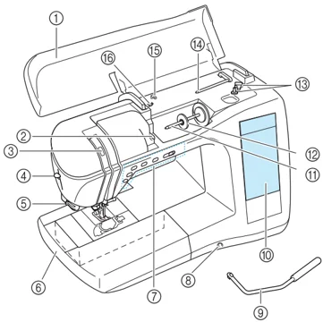
① Top cover Open the top cover to thread the machine and wind the bobbin. ② Thread guide plate Pass the thread around the thread guide plate when threading the upper thread. ③ Thread take-up lever check window Look through the window to check the position of the take-up lever. ④ Needle threader lever Use the needle threader lever when threading the needle automatically. ⑤ Thread cutter Pass the threads through the thread cutter to cut them. ⑥ Flat bed attachment with accessory compartment Store presser feet and bobbins in the accessory compartment of the flat bed attachment. Remove the flat bed attachment when sewing cylindrical pieces such as sleeve cuffs. ⑦ Operation buttons (5 buttons) and sewing speed controller Use these buttons to perform various operations, such as starting sewing and raising or lowering the needle. Slide the sewing speed controller to adjust the sewing speed while using utility stitches. ⑧ Knee lifter slot Insert the knee lifter into the slot. ⑨ Knee lifter Use the knee lifter to raise and lower the presser foot. ⑩ LCD (liquid crystal display) Stitch settings can be viewed and edited, and operations for using the machine can be displayed, and error messages appear in the LCD. ⑪ Spool pin Place a spool of thread on the spool pin. ⑫ Spool cap Use the spool cap to hold the spool in place. ⑬ Bobbin winder Use the bobbin winder when winding the bobbin. ⑭ Supplemental spool pin Use this spool pin to wind the bobbin thread while sewing or to sew with the twin needle. ⑮ Thread guide Pass the thread through this thread guide when winding the bobbin thread. ⑯ Bobbin winding thread guide Pass the thread around this thread guide when winding the bobbin thread.
■ Right-side/Rear View
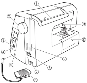
① Handle When transporting the machine, carry it by this handle. ② Handwheel Turn the handwheel toward you to sew one stitch or to raise or lower the needle. ③ USB connector Plug in a USB cable to connect a computer. ④ Touch pen holder Use the touch pen holder to hold the touch pen when it is not being used. ⑤ Foot controller jack Insert the plug on the end of the foot controller cord into the foot controller jack. ⑥ Foot controller Press the foot controller to control the speed of the machine. ⑦ Jack connector Insert the power cord into the jack connector. ⑧ Main power switch Use the main power switch to turn the machine ON and OFF. ⑨ Air vent Do not cover the air vent while the sewing machine is being used. ⑩ Feed dog position indicator Indicates whether the feed dogs are raised or lowered. ⑪ Presser foot lever Raise and lower the presser foot lever to raise and lower the presser foot.
NAMES OF MACHINE PARTS AND THEIR FUNCTIONS
Needle and Presser Foot Section
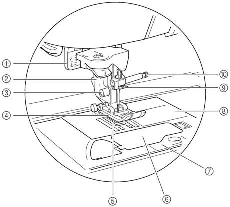
① Buttonhole lever Lower the buttonhole lever when sewing buttonholes and bar tacks.
② Presser foot holder The presser foot is attached to the presser foot holder.
③ Presser foot holder screw Use the presser foot holder screw to hold the presser foot holder in place.
④ Presser foot The presser foot consistently applies pressure to the fabric as it is sewn. Attach the appropriate presser foot for the selected stitch.
⑤ Feed dogs The feed dogs feed the fabric in the sewing direction.
⑥ Bobbin cover Open the bobbin cover to insert the bobbin.
⑦ Needle plate cover Remove the needle plate cover to clean the bobbin case and race.
⑧ Needle plate The needle plate is marked with guides to help sew straight seams.
⑨ Needle bar thread guide Pass the upper thread through the needle bar thread guide.
⑩ Needle clamp screw Use the needle clamp screw to hold the needle in place.
Measurements on the needle plate, bobbin cover and needle plate cover
The measurements on the needle plate and bobbin cover are references for patterns with a middle (center) needle position. The measurements on the needle plate cover is a reference for stitches with a left needle position.
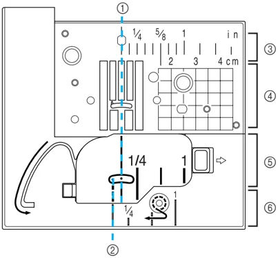
① For stitches with a middle (center) needle position ② For stitches with a left needle position ③ Middle (center) needle position ④ Middle (center) needle position ⑤ Middle (center) needle position ⑥ Left needle position
10
NAMES OF MACHINE PARTS AND THEIR FUNCTIONS
Operation Buttons
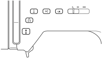
❶ “Start/Stop” button When this button is pressed, the machine sews a few stitches at a low speed, then begins sewing at the speed set by the sewing speed controller. Press this button again to stop sewing. This button lights up in a different color depending on the machine’s operating condition. Green: The machine is ready to sew or is sewing. Red: The machine cannot sew.
❷ “Reverse/Reinforcement Stitch” button This button is used to sew reinforcement stitches at the beginning and end of stitching. When this button is pressed, the machine sews 3 to 5 stitches in the same spot, then stops automatically. For straight and zigzag stitches that take reverse stitches, the machine sews reverse stitches (stitches sewn in the opposite direction) at low speed only while the “Reverse/ Reinforcement Stitch” button is held down.
❸ “Needle Position” button Use this button to change the sewing direction or for detailed sewing in small areas. Press this button to raise or lower the needle position. Press this button twice to sew a single stitch.
❹ “Thread Cutter” button Press this button after sewing to automatically trim the excess thread.
❺ “Presser Foot Lifter” button Press this button to lower the presser foot and apply pressure to the fabric. Press this button again to raise the presser foot.
❻ Sewing speed controller Slide the sewing speed controller to the left or right to adjust the sewing speed. Slide the controller to the left to sew at lower speeds. Slide the controller to the right to sew at higher speeds. Beginners should sew at a lower speed until they become familiar with the machine.
CAUTION
- Do not press the “Thread Cutter” button after the threads have already been cut. Otherwise, the needle may break, the threads may become tangled, or damage to the machine may occur.
Included Accessories
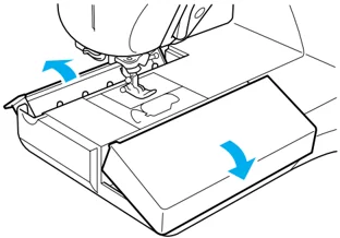
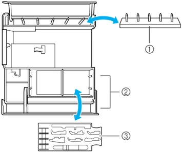
The accessories are stored in the flat bed attachment. Open the flat bed attachment as shown below.

❶ Bobbin stand (Place the bobbins on the pins to store them.) ❷ Storage space ❸ Presser foot storage tray (Store presser feet marked A, G, I, J, M, N, and R.)
11
NAMES OF MACHINE PARTS AND THEIR FUNCTIONS
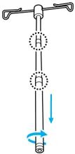
■ How to Assemble the Spool Stand
1 Fully extend the telescopic thread guide shaft, and then rotate the shaft until the two stoppers click into place.
2 Insert the telescopic thread guide into the round hole at the center of the spool support, and then use a screwdriver to securely tighten the screw from the reverse side.
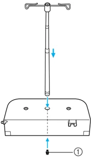
① Screw
Note Make sure that the stoppers on the telescopic thread guide shaft are firmly in place and that the top of the thread guide is parallel to the spool support. In addition, check that the shaft is straight up from the spool support.
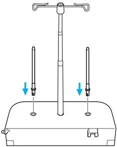
3 Firmly insert the two spool pins into the two holes in the spool support.
4 Open the upper cover of the machine. With your right hand, snap the cover toward the back to release the cover from the latch. Slide the upper cover to the right so that the pin on the left side is disengaged, and then remove the upper cover.
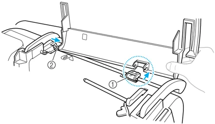
① Latch ② Pin
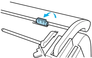
5 Raise the latch on the machine toward you.

NAMES OF MACHINE PARTS AND THEIR FUNCTIONS
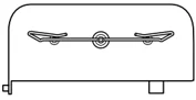
6 With the lower part of the stand between the handle and machine, slide the spool stand to the left so that the pin fits into the hole in the machine, and then fit the spool stand into the latch.
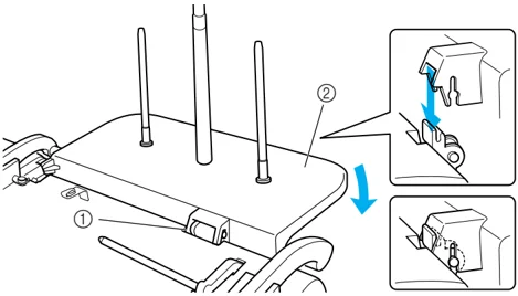
① Latch ② Spool stand
Note Make sure that the latch of the machine is positioned toward you and that the spool stand firmly fits into the groove in the latch.
Memo For details on using the spool stand, refer to the enclosed instruction sheet.
13
NAMES OF MACHINE PARTS AND THEIR FUNCTIONS
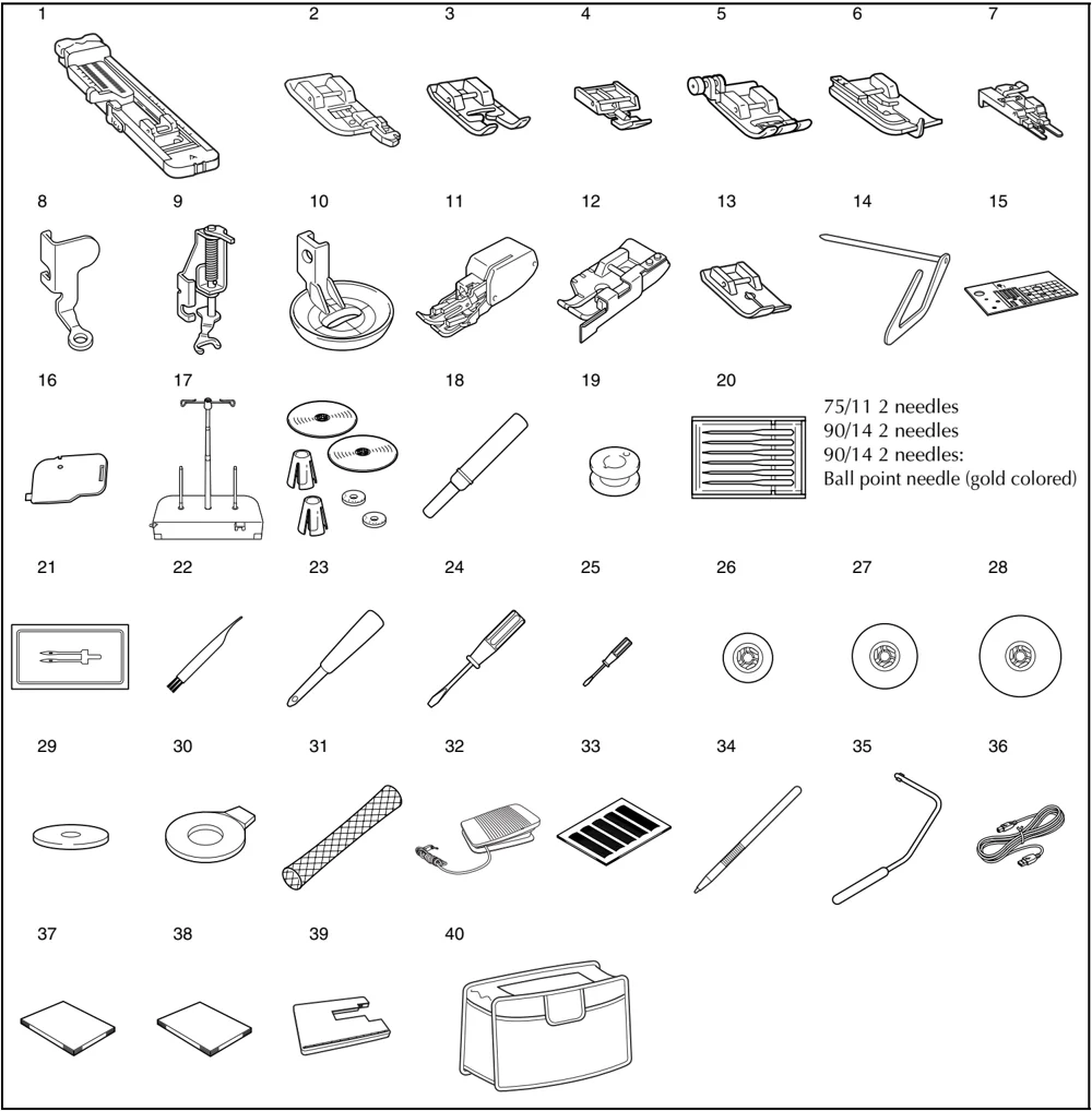
14
NAMES OF MACHINE PARTS AND THEIR FUNCTIONS
| No. | Part Name | Part Code | |
|---|---|---|---|
| U.S.A./ Canada | Others | ||
| 1 | Buttonhole foot “A” | X57789-151 | |
| 2 | Overcasting foot “G” | XC3098-051 | |
| 3 | Monogramming foot “N” | X53840-351 | |
| 4 | Zipper foot “I” | X59370-051 | |
| 5 | Zigzag foot “J” (on machine) | XC3021-051 | |
| 6 | Blind stitch foot “R” | X56409-051 | |
| 7 | Button fitting foot “M” | 130489-001 | |
| 8 | Free-motion quilting foot “C” | XE0765-001 | |
| 9 | Free-motion open toe quilting foot “O” | XE0767-001 | |
| 10 | Free-motion echo quilting foot “E” | XE0766-001 | |
| 11 | Walking foot | SA140 | F033N:XC2214-102 |
| 12 | □/□” quilting foot with guide | SA185 | F057:XC7416-252 |
| 13 | Straight stitch foot | XD0826-051 | |
| 14 | Quilting guide | SA132 | F016N:XC2215-002 |
| 15 | Straight stitch needle plate | XC8362-051 | |
| 16 | Cord guide bobbin cover (with single hole) | XC8449-051 | |
| 17 | Spool stand | XE0774-001 | |
| 18 | Seam ripper | X54243-051 | |
| 19 | Bobbin × 10 | SA156 | SFB:XA5539-151 |
| 20 | Needle set | X58358-051 | |
| 21 | Twin Needle | X59296-151 | |
| 22 | Cleaning brush | X59476-051 | |
| 23 | Eyelet punch | 135793-001 | |
| 24 | Screwdriver (large) | XC8349-051 | |
| 25 | Screwdriver (small) | X55468-051 | |
| 26 | Spool cap (small) × 2 | 130013-154 | |
| 27 | Spool cap (medium) × 2 One is on the machine. | X55260-153 | |
| 28 | Spool cap (large) × 2 | 130012-054 | |
| 29 | Spool felt | X57045-051 | |
| 30 | Disc-shaped screwdriver | XC1074-051 | |
| 31 | Spool net | XA5523-050 | |
| 32 | Foot controller | XD0501-051 (EU area) XC8816-051 (other area) | |
| 33 | Grid sheet set | SA507 | GS3:X81277-150 |
| 34 | Touch pen (stylus) | XA9940-051 | |
| 35 | Knee lifter | XA6941-052 | |
| 36 | USB cable | XD0745-051 | |
| 37 | Operation Manual | XE0783-001 | |
| 38 | Quick Reference Guide | XE0996-001 | |
| 39 | Wide table | XE0802-001 | |
| 40 | Soft cover | XE1121-001 |
Memo
- For details on using parts 13, 17 and 39, refer to the enclosed instruction sheet.
- Always use accessories recommended for this machine.
- The screw for the presser foot holder is available through your authorized dealer (part code: XA4813-051).
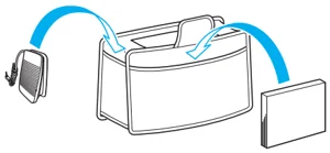
- This operation manual and the foot controller can be stored in the soft cover.

Memo
(For U.S.A. only)
Foot controller: Model T
This foot controller can be used with this machine model QC-1000.
Options
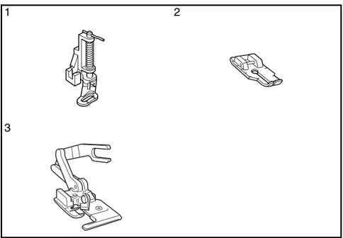
| No. | Part Name | Part Code | |
|---|---|---|---|
| U.S.A./ Canada | Others | ||
| 1 | Quilting foot | SA129 | F005N:XC1948-002 |
| 2 | 1/4" quilting foot | SA125 | F001N:XC1944-052 |
| 3 | Side cutter foot | SA177 | F054:XC3879-002 |
Memo
- All specifications are correct at the time of printing.
- Please be aware that some specifications may change without notice.
Note
Visit your authorized dealer for complete listing of optional accessories available for your machine.